
Part-transfer or workpiece-presentation interface
Specified as part of the relevant application and system configuration.
Automation-ready configuration
Inline laser soldering is an engineering integration project rather than a simple transfer of a bench process into a conveyor. The process head, position references, workholding, part presentation, safety interface and handling sequence must be considered together so that the soldering process remains appropriate for the production concept.
What the system is
Inline laser soldering is an engineering integration project rather than a simple transfer of a bench process into a conveyor. The process head, position references, workholding, part presentation, safety interface and handling sequence must be considered together so that the soldering process remains appropriate for the production concept.
Machine structure
The system connects material delivery, energy, positioning, workholding and programmable control. The precise relationship is defined through the application and sample process.
Specified as part of the relevant application and system configuration.
Specified as part of the relevant application and system configuration.
Specified as part of the relevant application and system configuration.
Specified as part of the relevant application and system configuration.
Specified as part of the relevant application and system configuration.
Specified as part of the relevant application and system configuration.
Process workflow
Integration options
SMEMA or equivalent interface only when project requirements define it
Part detection and fixture confirmation
Handling integrator coordination
Vision-guided correction when the application requires it
Traceability interface review as a project-specific item
Engineering notes
The available information supports a practical engineering conversation. The final configuration follows the selected system and sample result.
The supplied materials support customized precision automation positioning, not a universal inline specification.
Cycle time needs to be evaluated with the part path, number of dots, handling and inspection sequence.
Any connection standard or traceability approach should be documented before final integration.
Real process evidence
Real supplied process video and frames show the head, workpiece, fixture and repeat sequence without audio autoplay.
Supplied process video
Supplied footage showing the workpiece / fixture and repeated jetting context.
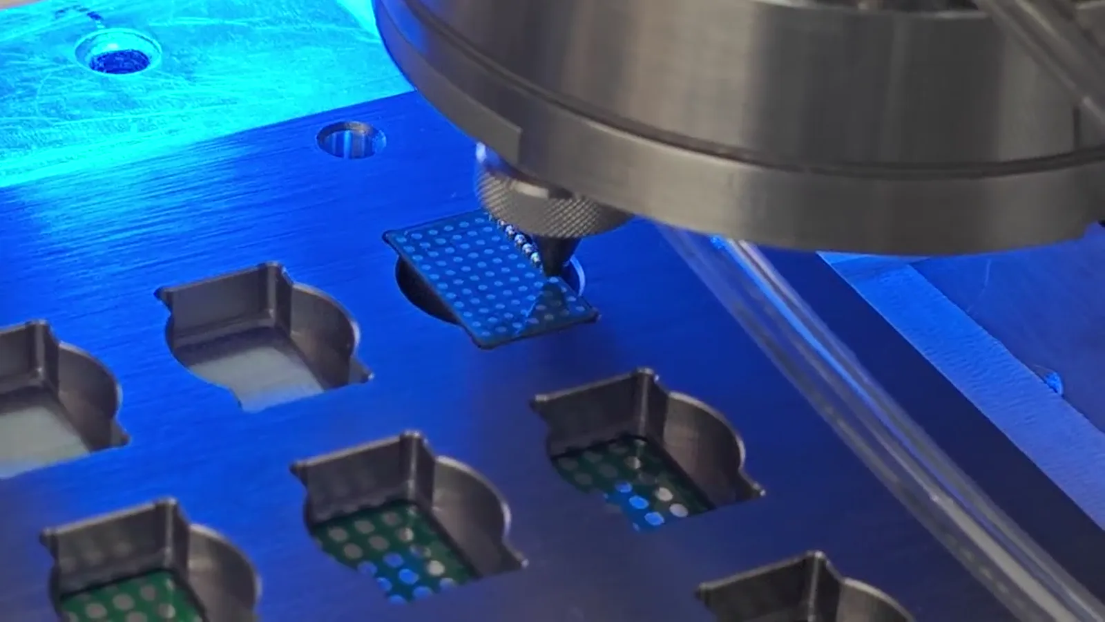
The supplied process video shows a jetting head, fixture support and multiple workpiece positions.
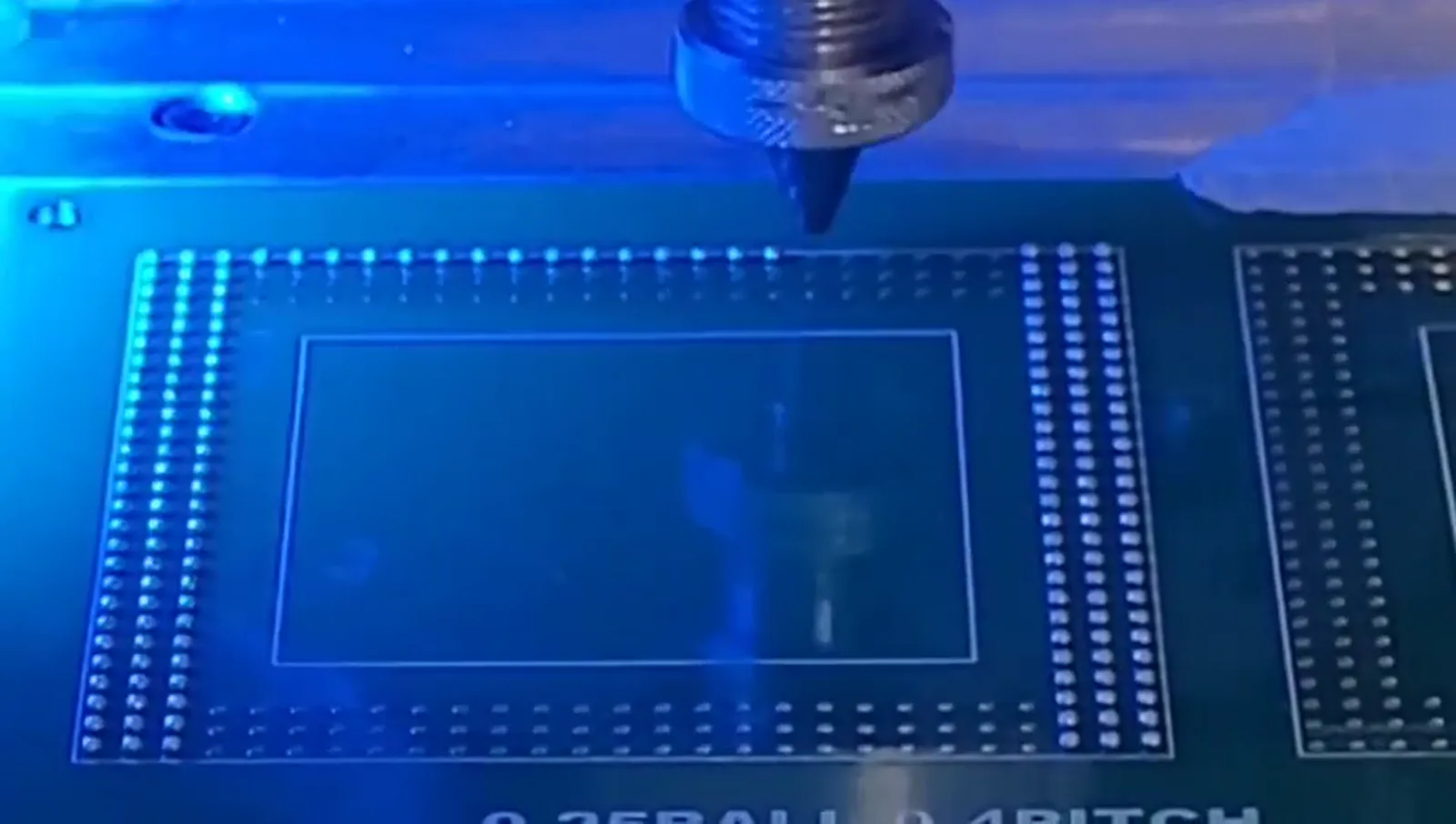
Array-processing context from supplied process footage.
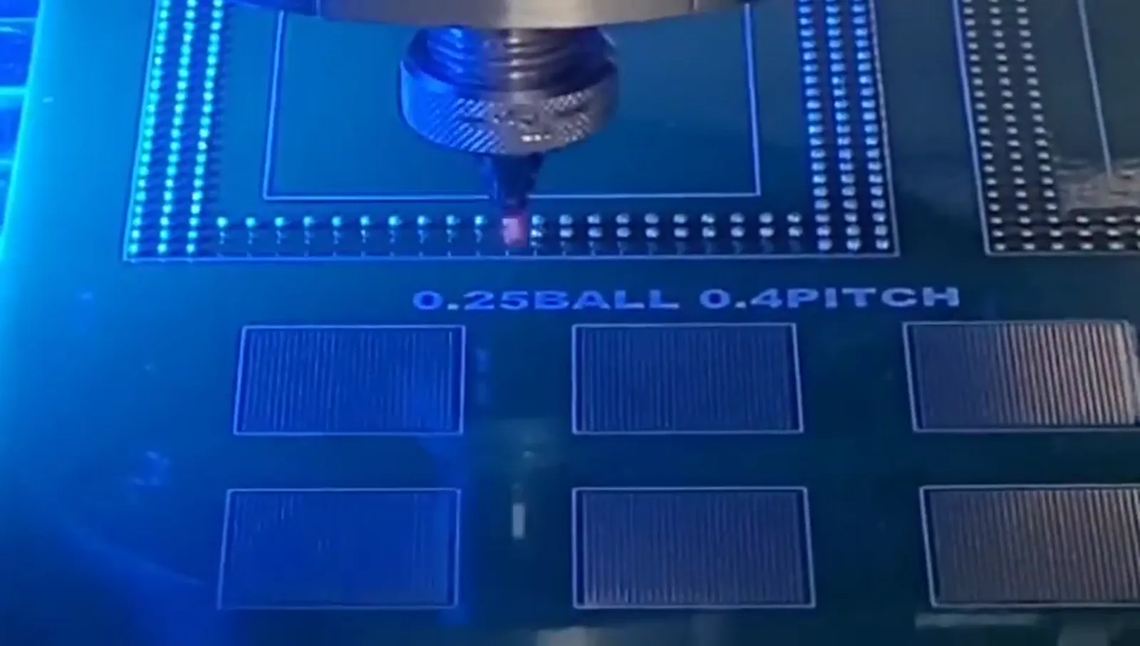
Demonstration of 0.25 mm solder ball processing on a 0.4 mm pitch test pattern.
Visible FAQ
Answers remain application-led and avoid generic performance promises.
No. Part presentation, access, fixture concept, handling, recipe change and quality requirements also affect the configuration.
After the soldering process is feasible on representative samples and the product flow has been defined.
Related engineering paths
Internal links are selected for application relevance rather than placed as an artificial SEO list.
Application considerations for localized laser solder ball jetting around camera-module assemblies.
Explore →Engineering evaluation factors for laser soldering of VCM-related components.
Explore →Considerations for localized solder-ball jetting on flexible printed circuits.
Explore →A process-evaluation approach to sensor soldering with localized laser heat input.
Explore →Have a micro-soldering application to evaluate?
Share drawings, sample photographs or soldering requirements. The engineering discussion can connect the component to a suitable process and machine configuration.