
Solder ball application
Approximate range in supplied technical information for a documented configuration.
Precision laser soldering automation
Precision, non-contact laser soldering solutions for camera modules, FPC, sensors, MEMS, connectors and microelectronic assemblies.
Technology introduction
Different soldering technologies are suitable for different manufacturing requirements. Laser solder ball jetting is considered when the application calls for localized heating, controlled solder delivery, access to small or confined joints, repeatable positioning or a path toward automated processing.
The technology should not be separated from the assembly around it. A useful process combines solder-ball feeding, laser melting, gas-assisted transfer, motion, fixture design, position reference, software and application engineering.
How solder ball jetting works →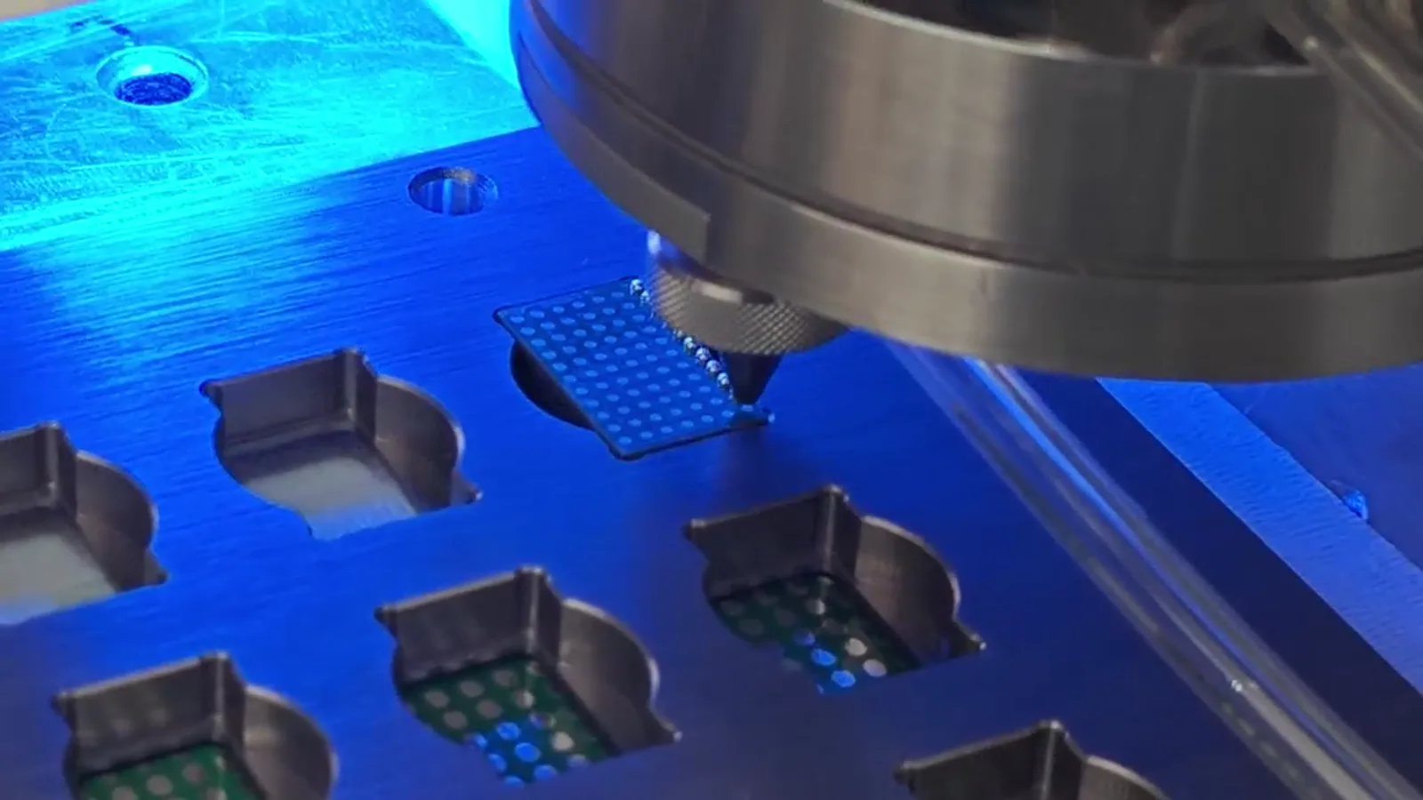
Process map
The documented sequence connects material delivery, nozzle relationship, laser melting, gas-assisted transfer and the supported workpiece. The diagram is explanatory: configuration, fixture and inspection conditions remain application specific.

Engineering sequence
Ball delivery, melting and transfer are practical events; fixture support, motion and a selected reference make them meaningful for the actual component.
A controlled feed presents solder balls to the process head.
One ball is isolated before the next soldering cycle.
Programmable motion and vision reference the intended joint location.
Laser energy is directed to melt the ball at the nozzle.
Gas pressure transfers the molten solder toward the soldering position.
The localized process forms the required joint on the workpiece.
The process sequence continues according to the programmed path.
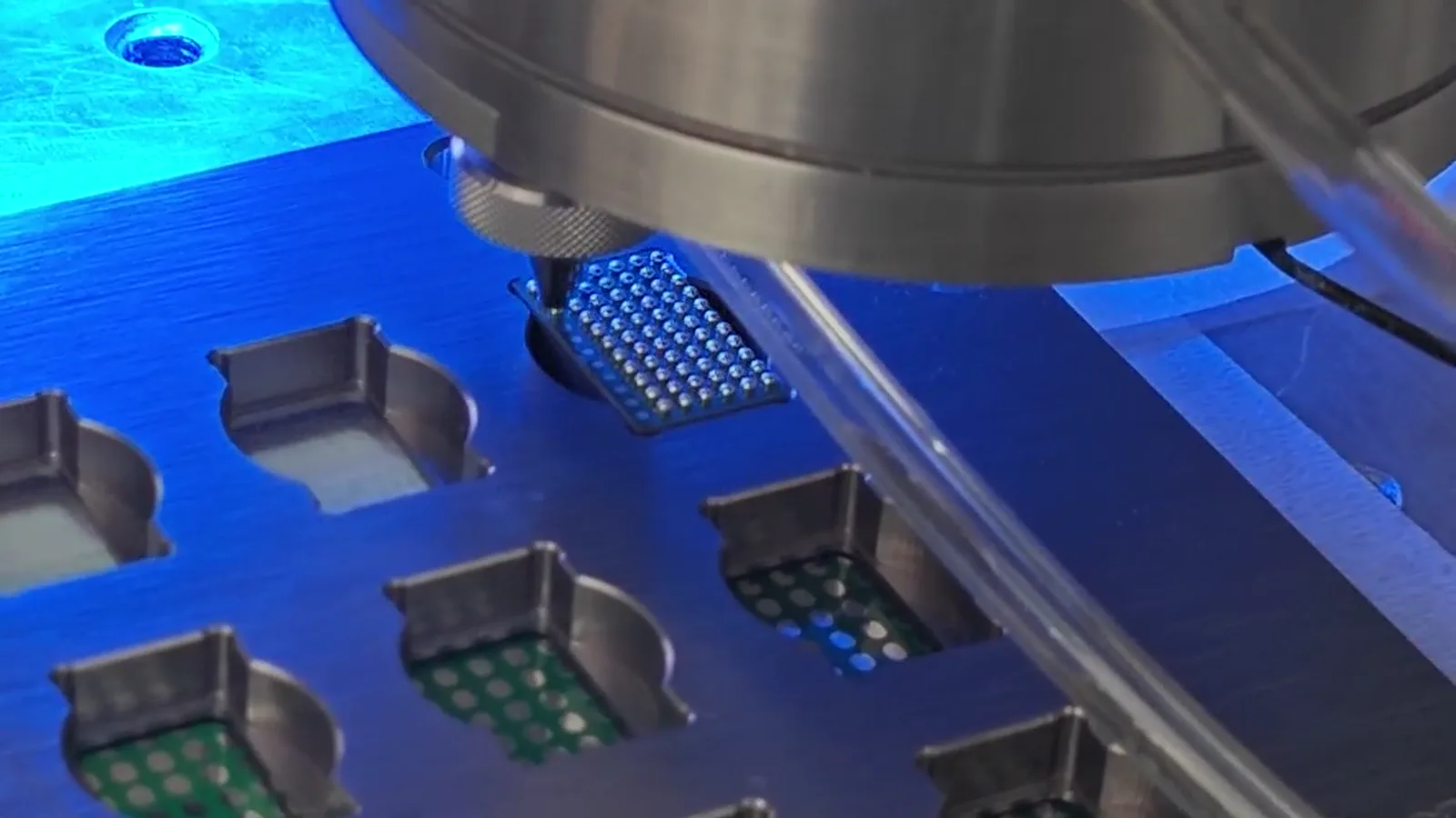
Vision, fixture and recipe
A supplied machine-operation frame can show the working environment, but it does not identify a universal machine architecture or catalogue configuration. It shows the relationship that needs to be designed: a supported workpiece, practical access for the head, a repeatable reference and a programmed path suited to the selected application.
CCD vision may help locate a usable reference feature when a mechanical datum alone is not sufficient. The camera result must be calibrated to the motion coordinates and physical jetting point. A fixture can support delicate areas, protect nearby features, establish orientation and make a selected process condition repeatable during a sample trial.
Explore vision positioning →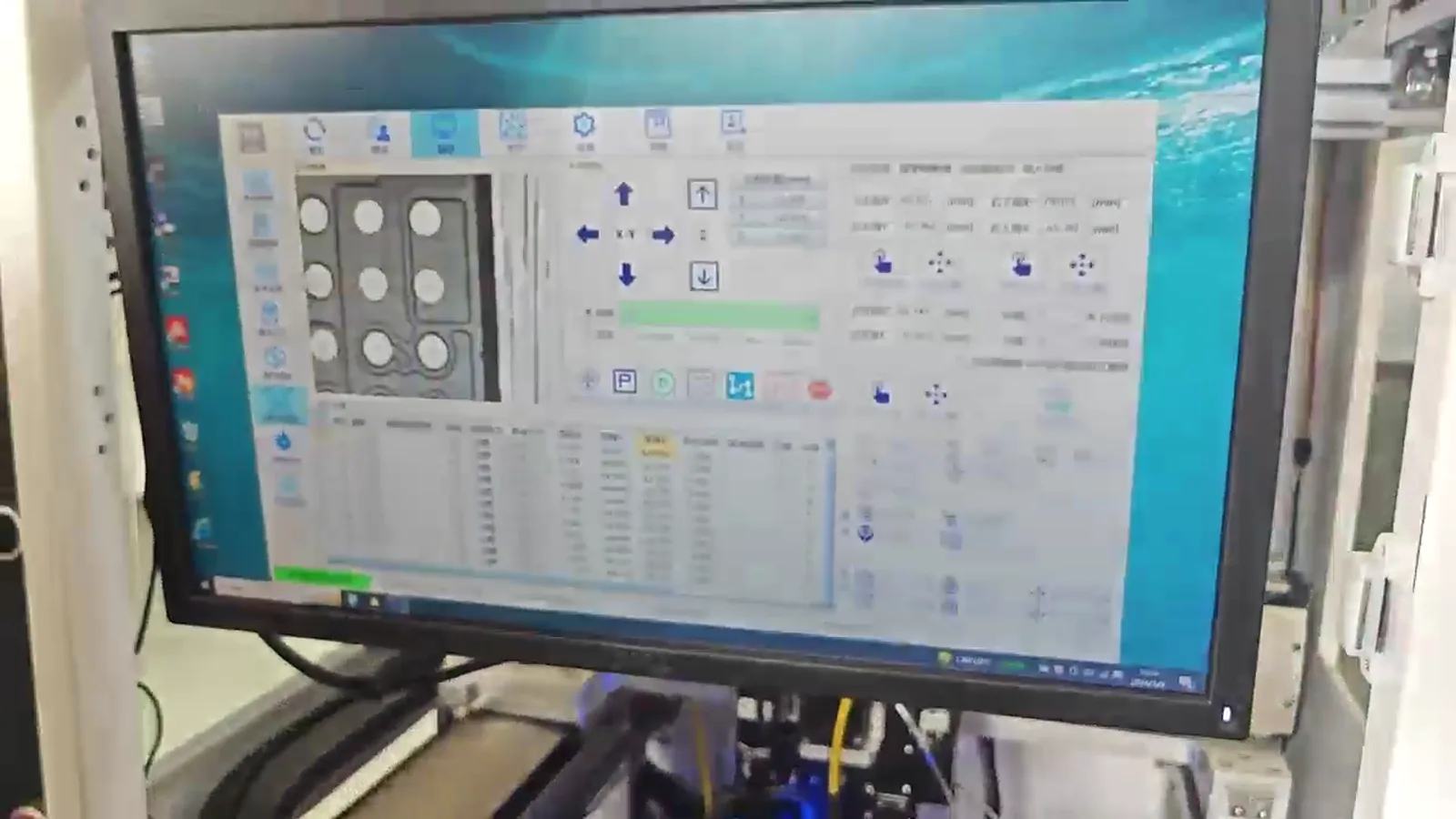
Documented technical references
The values frame an engineering discussion and are intentionally shown with their documented scope rather than merged into a universal machine specification.
Approximate range in supplied technical information for a documented configuration.
A documented maximum; complete cycle time also depends on motion, handling, inspection and sequence.
Value stated for one described system; fixture, datum and component conditions remain relevant.
Referenced options depend on selected machine and application requirement.
Specifications depend on machine configuration and application requirements. Do not treat values from different systems as identical specifications for every model.
Process and sample evidence
Every image is from supplied process or sample material. Captions describe what is visible and do not assign customer identity, production qualification or undocumented performance.
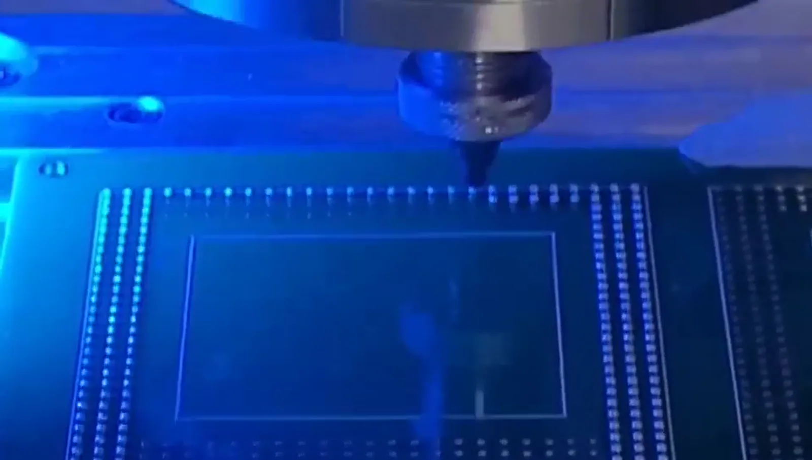
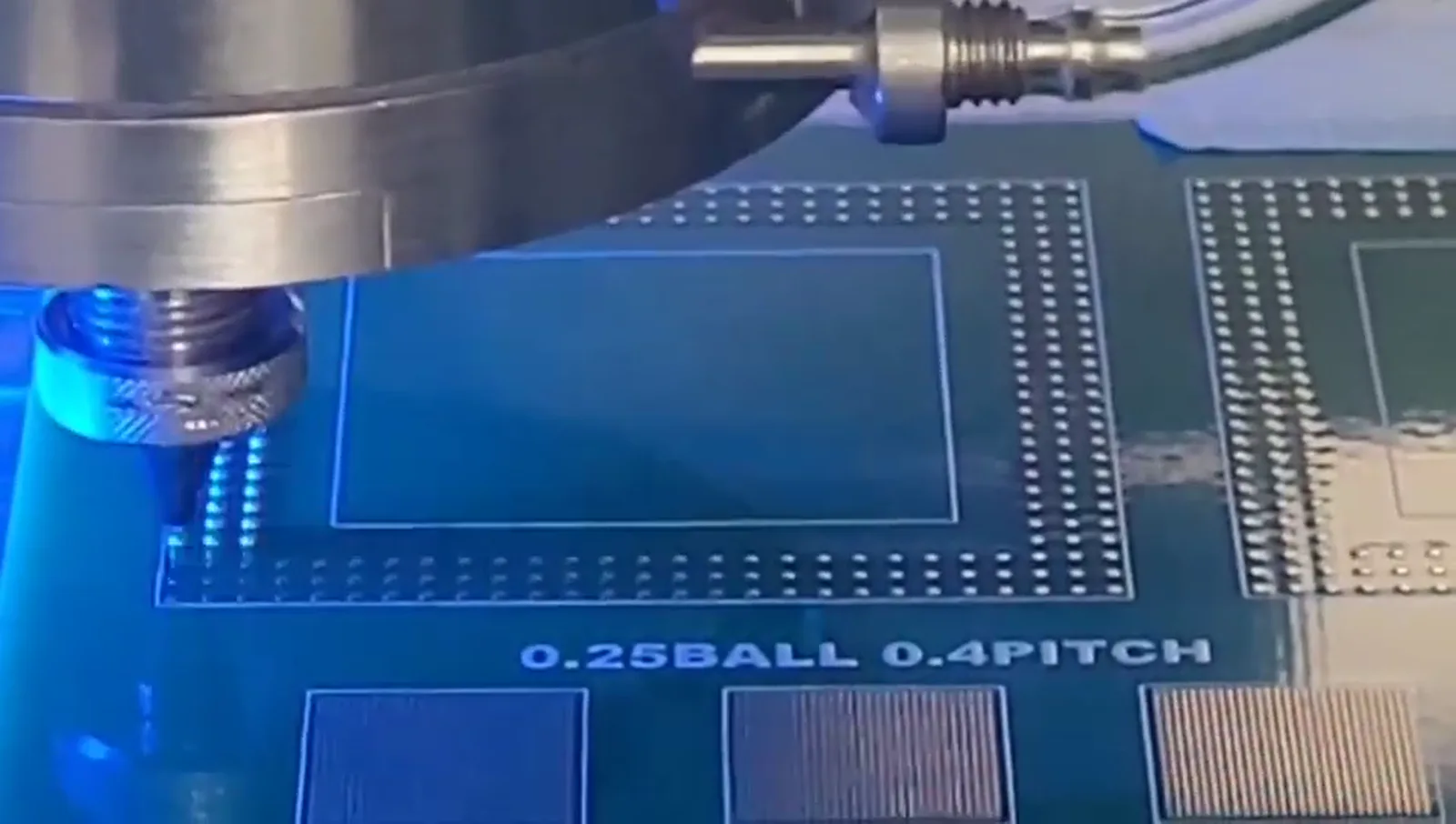
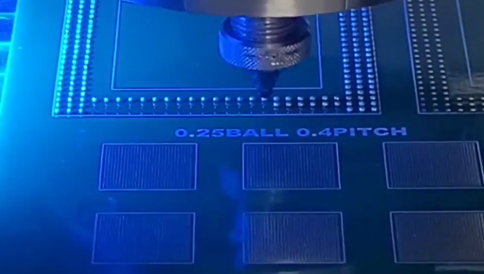
Repeated positions remain connected to fixture support, reference and the programmed path.
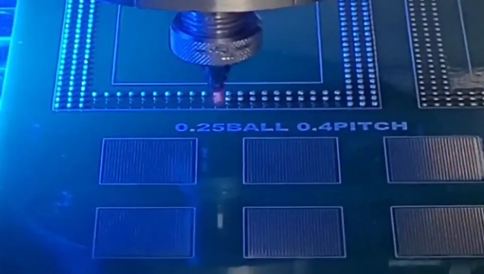
Demonstration of 0.25 mm solder ball processing on a 0.4 mm pitch test pattern; not a universal minimum specification.
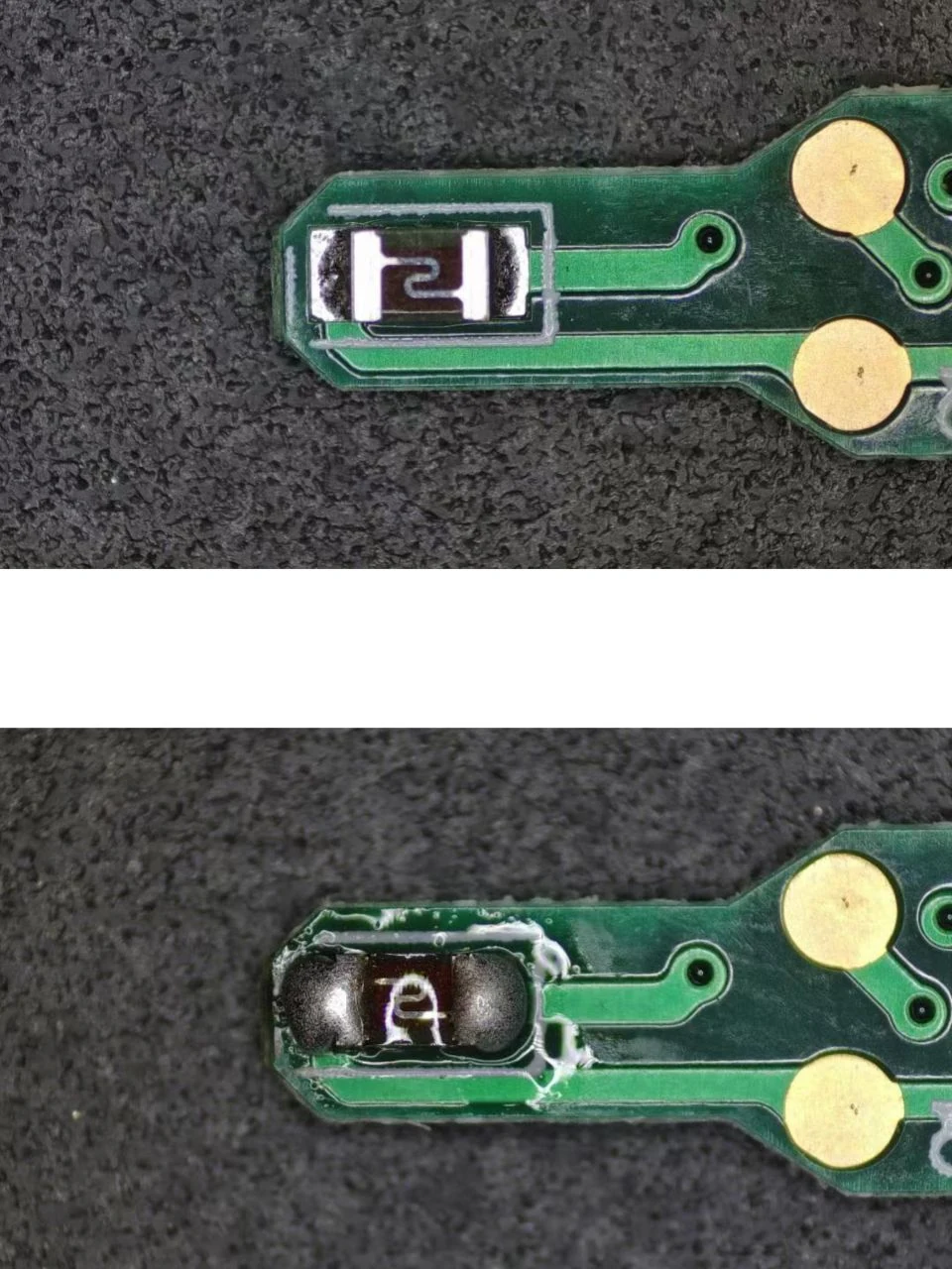
Supplied component sample imagery for process discussion, not a customer case study.
Real process video
Process footage is kept direct and technical: the delivery head, workpiece relationship and repeated operating sequence are visible without marketing overlay. It provides process context, not a generic capability claim.
Solder ball delivery
Individual balls enter a controlled path before the soldering action.
Local process event
Laser melting and transfer must be assessed with the real component and fixture.
Reference and sequence
Motion, data and inspection connect the individual event to a programmed process.
Supplied process video
Supplied processing footage showing solder-ball jetting and the workpiece / fixture relationship.
Real sample context
Before-and-after photography gives the conversion discussion a technical starting point. Visual appearance must still be assessed against the actual component, process record and customer-defined inspection requirement.
Real supplied sample imagery
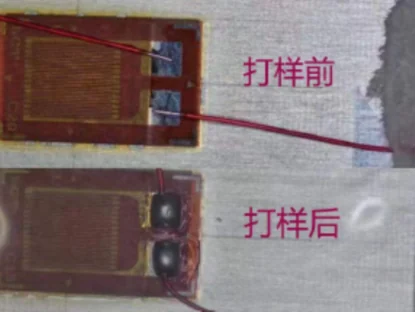
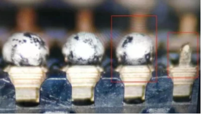
Supplied sample imagery for process discussion. Visible appearance does not establish customer identity, qualification or a result for another design.
Applications and configurations
Application pages describe potential process considerations; system pages explain configuration paths. Neither substitutes a general label for representative sample evaluation.
Technical table
The table preserves the configuration scope behind the visual data chapter, so readers can move from a fast visual overview to the original technical context.
Documented technical information — values are not combined as a universal specification.
| Parameter | Documented information | Scope |
|---|---|---|
| Solder ball application | Approximately 0.2–0.9 mm | A documented configuration; final selection follows joint geometry and evaluation. |
| Maximum soldering frequency | Up to 6 dots/s | Documented maximum; not complete machine cycle time. |
| Vision positioning | ±10 μm | A documented system; fixture, datum and component conditions remain relevant. |
| Laser configuration | 100 / 200 W | Referenced configuration options; not a universal model specification. |
Specifications are configuration dependent. Final machine configuration is determined after application and sample evaluation.
Process development
Share component information, photographs, drawings and the current method. The process evaluation can connect joint geometry, fixture, position reference, sample observations and a potential system configuration.
Send Your Sample for Evaluation →Engineering RFQ
Share the available information so the discussion can focus on the joint, component, process requirement and appropriate next step. Fields marked with * are required.
Submitted enquiries and attachment records are stored for engineering review. Direct WhatsApp and email remain available for immediate contact.