
Solder ball application
Approximate range for a documented configuration; final selection follows joint geometry and sample evaluation.
Precision electronics system
This configuration brings solder ball feeding, laser heating, guided jetting, motion control and process programming into one engineered platform. It is intended for precision-electronics work where a soldering method must be evaluated against the joint geometry, component material, access and production requirement.
What the system is
This configuration brings solder ball feeding, laser heating, guided jetting, motion control and process programming into one engineered platform. It is intended for precision-electronics work where a soldering method must be evaluated against the joint geometry, component material, access and production requirement.
The documented process brings individual-ball delivery, laser melting at the nozzle, guided transfer, fixture support, motion, position reference and recipe control into one application-led sequence. The relationship becomes useful only when it is defined around the actual joint and workpiece.
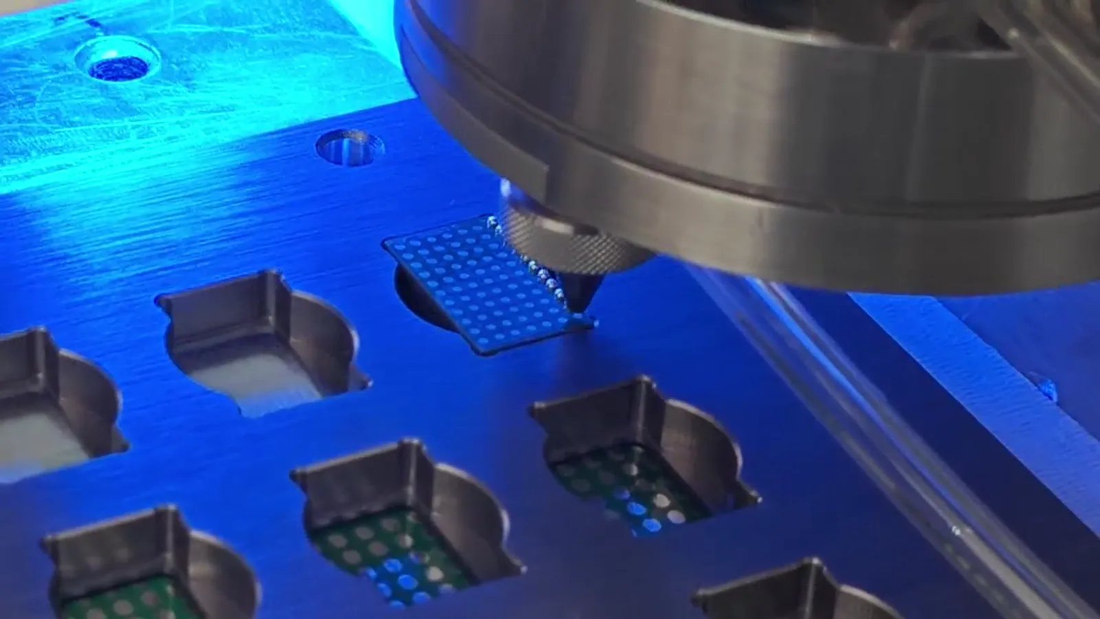
Machine architecture
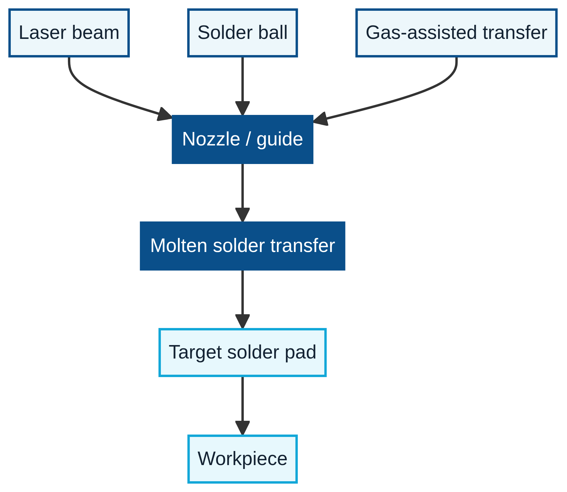
The feed, nozzle, laser, fixture, motion, vision and recipe relationship can be read as a physical chain—not as a detached catalogue of components.
Presents solder balls to the guide path. Feed condition and ball selection are checked against the intended joint.
Energy configuration belongs to the documented process; the selected setting is not universal across applications.
Nozzle access and working relationship depend on the actual component and fixture.
A vision reference can support a defined image feature or correction; calibration and fixture repeatability remain part of the same chain.
Coordinates the programmed path between head and supported workpiece, alongside the selected sequence and joint count.
Supports, protects and references the application-specific component so the process relationship can be repeated.
Vision and reference chain
The source material describes solder ball application approximately from 0.2 to 0.9 mm for a documented configuration.
Maximum frequency, positioning and laser selection are configuration dependent.
A documented system describes vision positioning of ±10 μm and 100 / 200 W laser configuration; these values should not be applied to every build.
Read about vision positioning →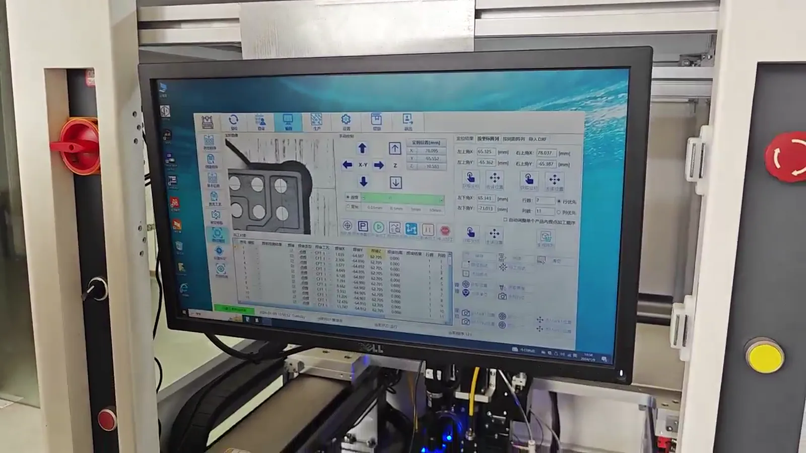
Documented technical references
The values below are source-supported references. They are kept separate from the visual machine story so a reader can see both the operating context and the scope of each value.
Approximate range for a documented configuration; final selection follows joint geometry and sample evaluation.
Documented maximum, not complete machine cycle time.
A documented system; fixture, datum and component conditions remain relevant.
Referenced configuration options, not a universal model specification.
Specifications are configuration dependent. Final machine configuration is determined after application and sample evaluation.
Real process and sample context
The images show supplied process or sample context. They do not establish a customer identity, production qualification, reliability result or universal capability.
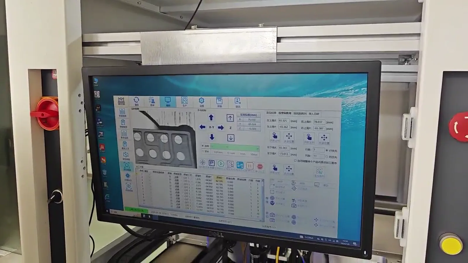
Fixture support defines the workpiece relationship; the exact fixture follows the part.
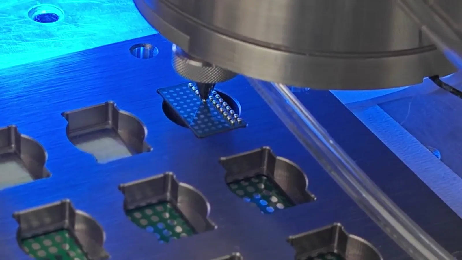
Programmed motion and repeat processing remain connected to the selected fixture and path.
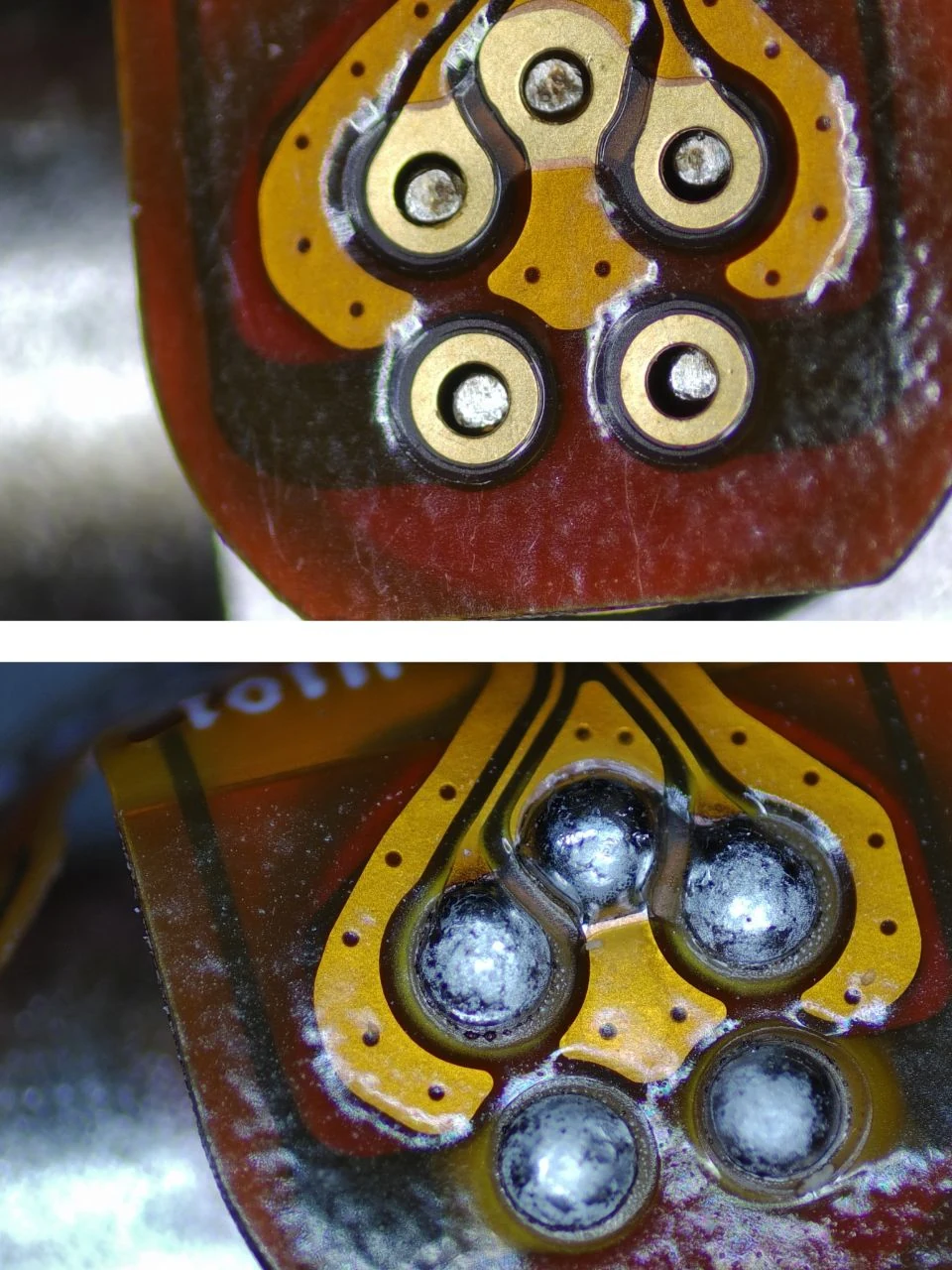
Visual sample context supports discussion; it does not replace the owner’s inspection plan.
Technical table
Use the table as a discussion aid, then validate the complete process with representative components and customer-defined criteria.
Documented technical information — values are not combined as a universal specification.
| Parameter | Documented information | Scope |
|---|---|---|
| Solder ball application | Approximately 0.2–0.9 mm | A documented configuration; final selection follows joint geometry and evaluation. |
| Maximum soldering frequency | Up to 6 dots/s | Documented maximum; not complete machine cycle time. |
| Vision positioning | ±10 μm | A documented system; fixture, datum and component conditions remain relevant. |
| Laser configuration | 100 / 200 W | Referenced configuration options; not a universal model specification. |
Specifications are configuration dependent. Final machine configuration is determined after application and sample evaluation.
Visible joint evidence
Visible joint appearance can guide a process conversation. It does not establish metallurgy, reliability, customer ownership or a result for an unrelated design.
Real supplied sample imagery
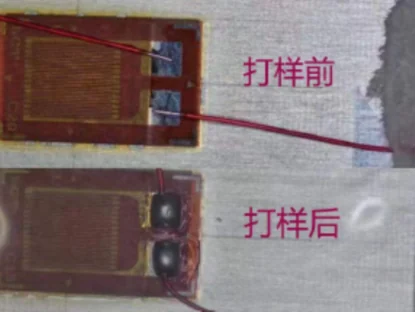
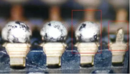
Supplied imagery is presented for process discussion. Final acceptance follows the actual component, record and customer-defined inspection criteria.
Authorized industry reference
These approved external references help distinguish an operator-access platform from a cabinet-style workcell. They are deliberately labelled as third-party reference imagery, not as Dayan equipment.
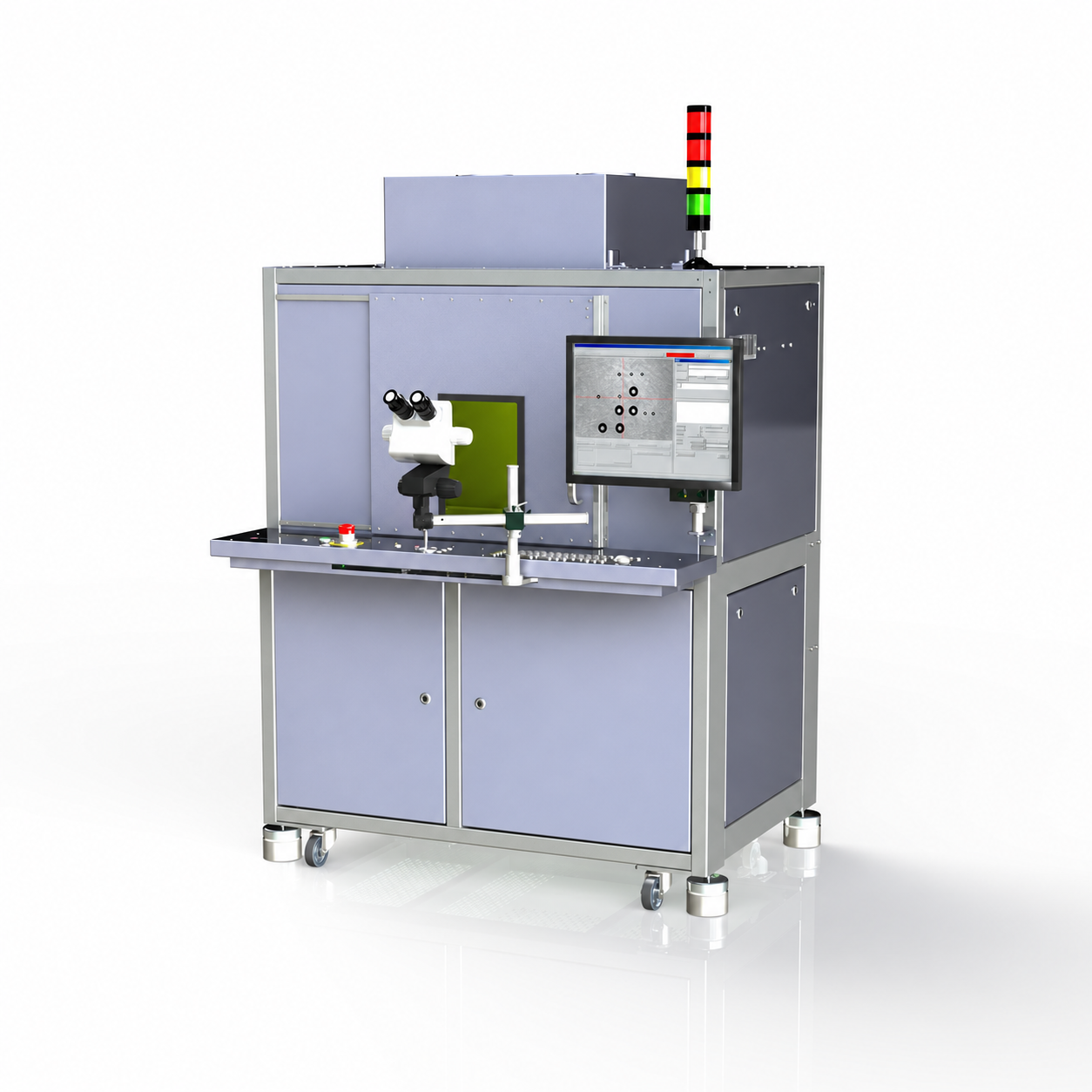
Authorized third-party equipment reference. Brand marks and source text have been removed; this is not a Dayan product photograph or specification claim.
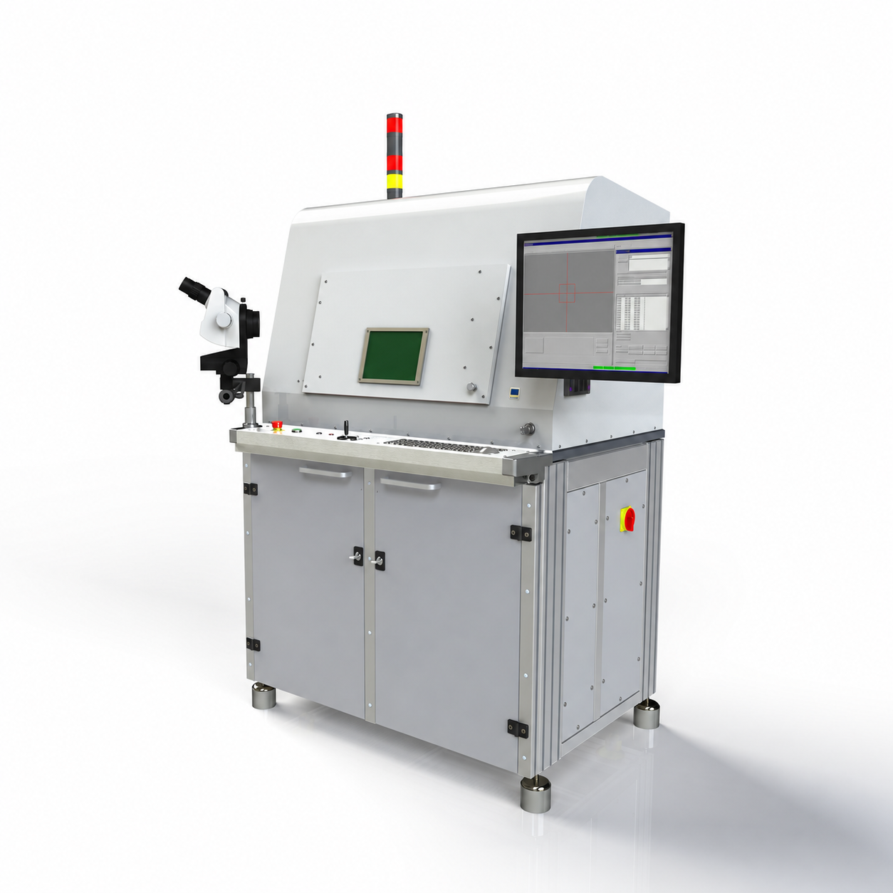
Authorized third-party equipment reference. Brand marks and source text have been removed; it illustrates a platform form factor only, not a Dayan product identity.
Supplied process video
Supplied process footage showing the workpiece, fixture and repeated jetting context.
Configuration follows process evidence
Review component and pad information
Confirm ball diameter and fixture approach
Establish position references
Develop laser and jetting parameters
Review trial soldered samples
Define the appropriate system configuration
Standalone workcell arrangement
Fixture-specific workholding
Vision-assisted positioning where required
Safety enclosure and operator interface
Connection to an automated handling concept when applicable
Visible FAQ
The working platform can be configured around the application. Final hardware, workholding, vision and automation scope should follow process evaluation.
Potential feasibility should be checked with drawings, photographs and representative samples before machine selection.
Related engineering paths
Internal links are selected for application relevance rather than placed as an artificial SEO list.
Application considerations for localized laser solder ball jetting around camera-module assemblies.
Explore →Engineering evaluation factors for laser soldering of VCM-related components.
Explore →Considerations for localized solder-ball jetting on flexible printed circuits.
Explore →A process-evaluation approach to sensor soldering with localized laser heat input.
Explore →Have a micro-soldering application to evaluate?
Share drawings, sample photographs or soldering requirements. The engineering discussion can connect the component to a suitable process and machine configuration.