Potential connector application

Connector Laser Soldering

Connectors may present rows of terminals, limited line-of-sight and material combinations that make a localized soldering review worthwhile. The process concept must match the actual terminal and pad geometry, fixture support and desired sequence.

Application challenge

Start with the real assembly environment

The central engineering issue is reliable access to each terminal without compromising surrounding plastic, metal or adjacent connections.

Joint geometry

Define the working envelope

Evaluation considers terminal pitch, pad shape, coplanarity, approach angle, connector body clearance and the part datum available for programming.

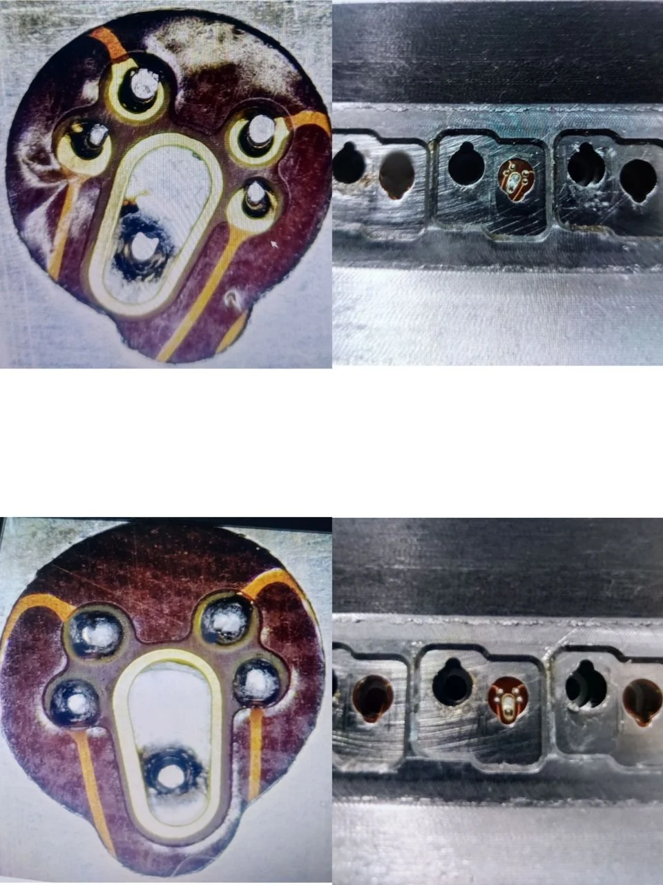
Connector geometry and pin access

Application-specific engineering questions

Supplied process and sample evidence supports the reading experience without being presented as an undocumented customer project.

01

The terminal path matters as much as the pin count

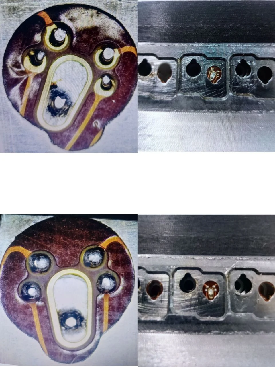
Connector assemblies may contain rows of terminals, nearby plastic features and constrained approach angles. A process evaluation maps each target location, terminal-to-terminal clearance, available nozzle path and the fixture support that keeps the connector in a usable datum.
02

Sequential processing needs an intentional reference

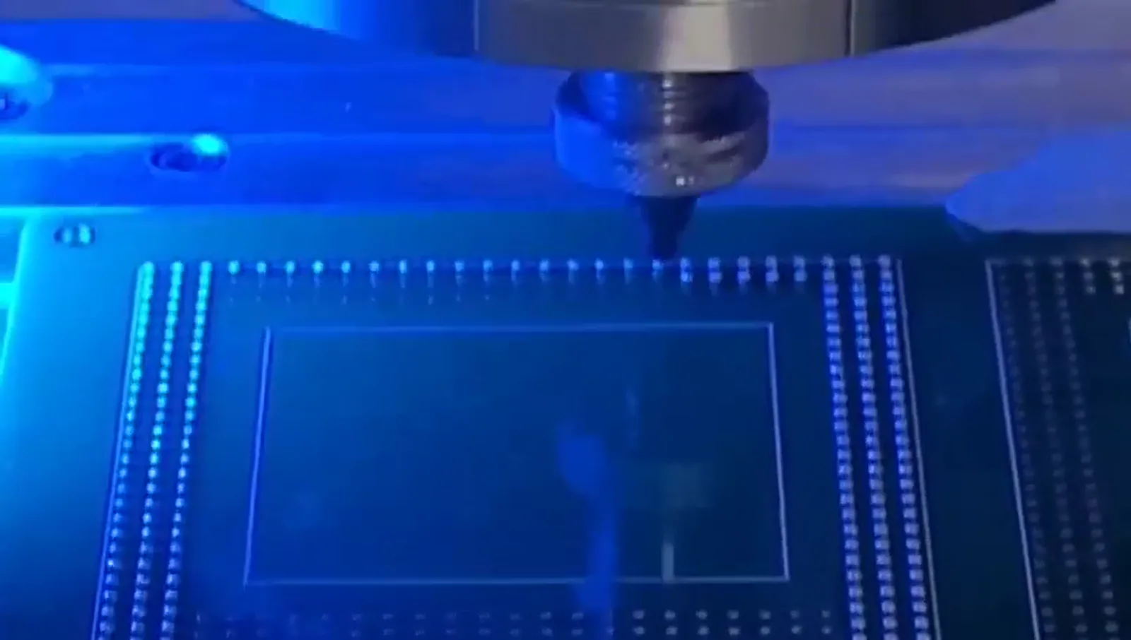
Multiple joints make path planning, motion travel and part presentation relevant. A stated dot frequency is not complete cycle time: the full sequence also contains handling, fixture actions, position reference and any inspection steps.

03

Use samples to establish the right configuration

The delivered solder volume and local heating should be considered together with the terminal and pad geometry. A single-station fixture, dual-station arrangement or custom cell is selected after that process relationship has been examined.

Application development guide

Move from a component label to a defined process question

Connector work is often governed by terminal geometry, spacing, approach path and repeatable positioning across multiple locations. A useful evaluation maps the target sequence instead of relying on pin count or a headline dot rate.

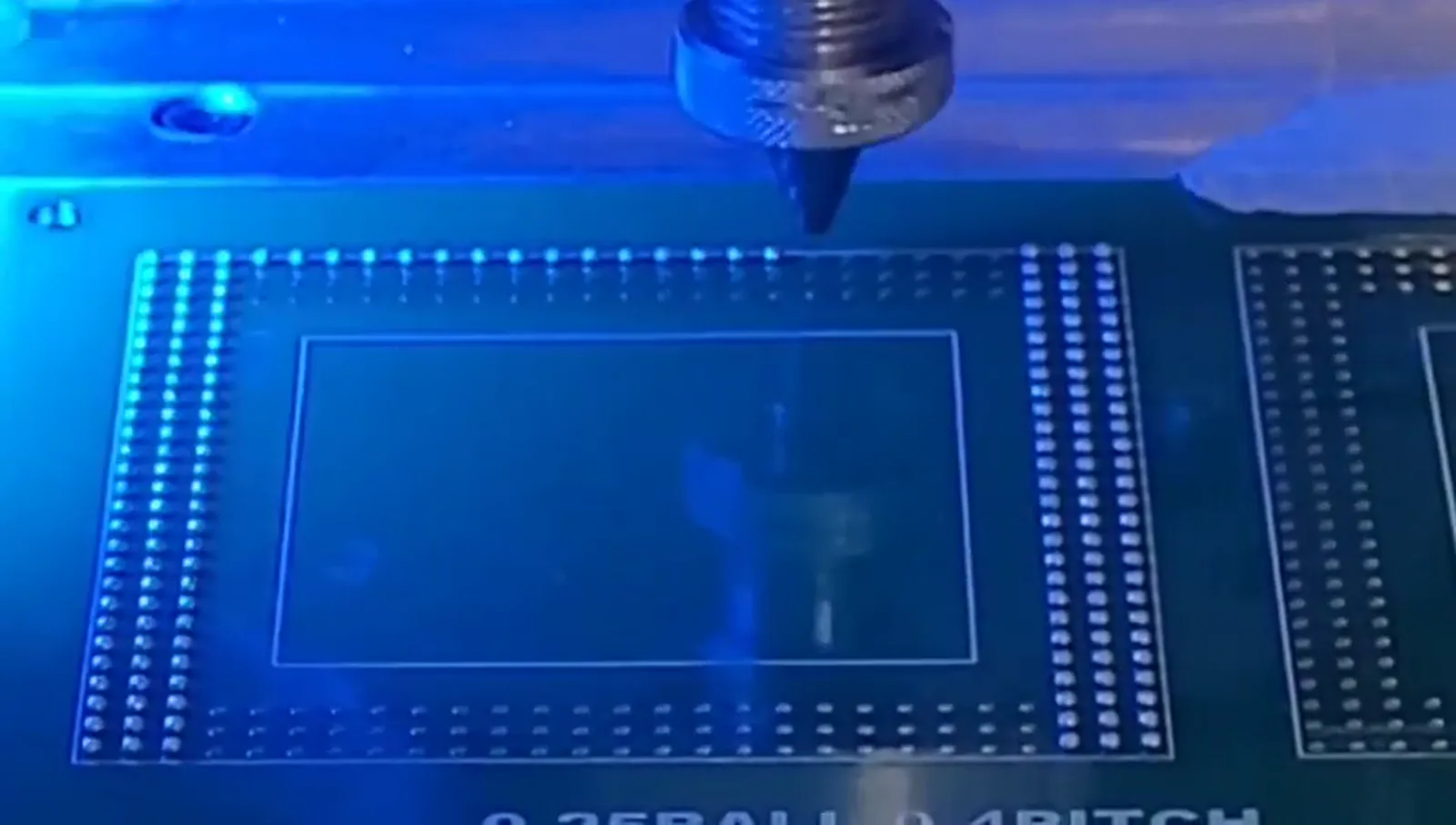
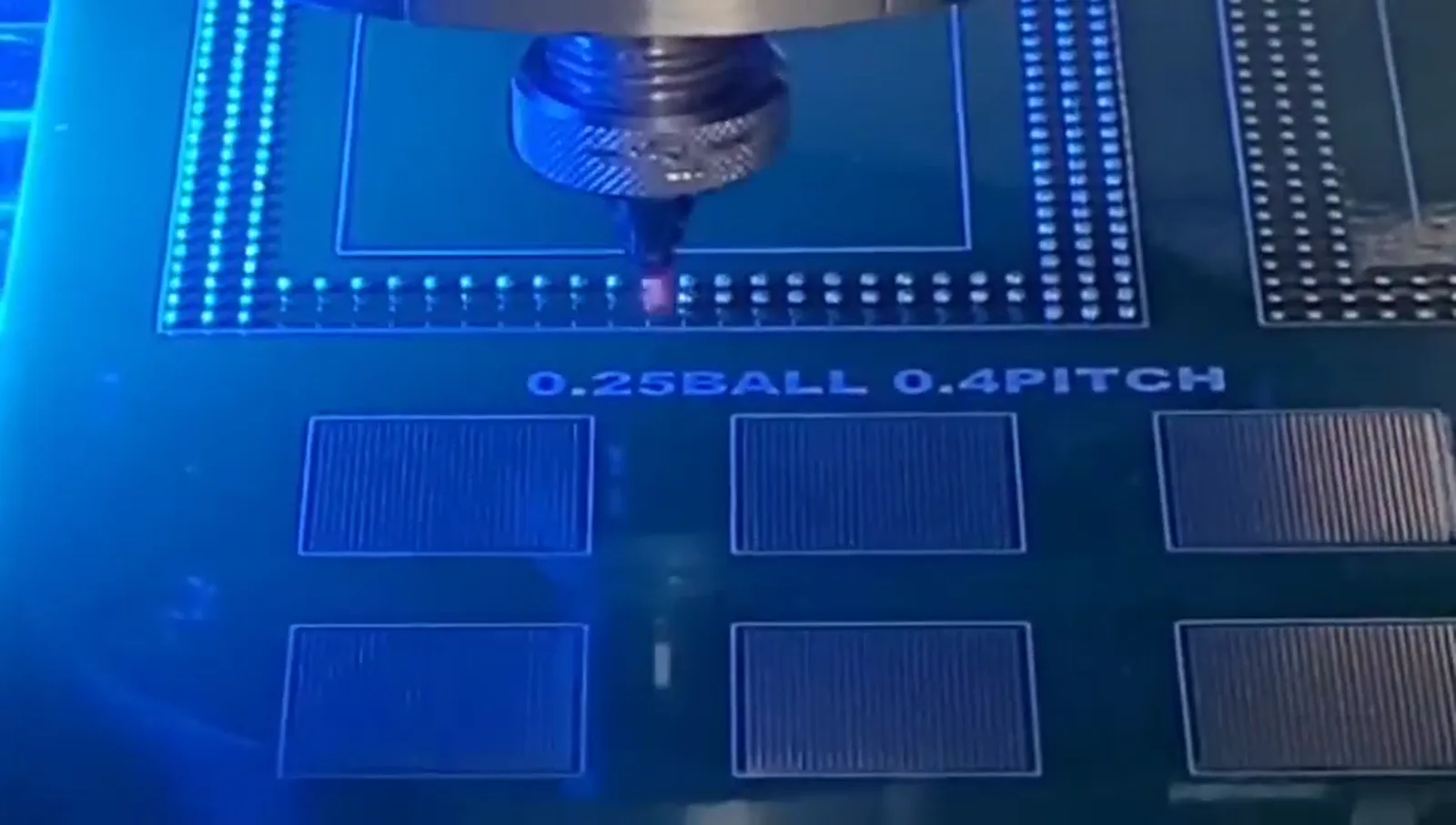
Supplied process frame of a nozzle over an array-oriented localized soldering sequence
Supplied array-process context for considering multiple joints and sequential access; connector identity is not asserted.

Evidence-aware process context

Use real supplied visuals to frame the review, not to overstate the result

The visible process relationship is useful for discussing access, fixture support, motion and position reference. It does not prove a material, industry or qualification claim for an unlabelled sample. The final process path should follow the component information and a representative evaluation.

Prepare a sample evaluation →

05

Map terminal-to-terminal access

Rows of terminals and nearby plastic or metal features can restrict nozzle approach even when the target pad appears open in a single photograph. Document terminal profile, pad shape, clearance, connector body position and the direction from which the process head must approach. The fixture needs to hold the part in a stable datum while preserving the required working envelope. This information is the starting point for a process trial rather than a promise based on connector category alone.

06

Build the sequence around the full path

Multiple joints introduce motion travel, point order, fixture action, part presentation and potential reference checks. The supplied source identifies up to 6 dots/s for one configuration, but that does not describe the complete connector cycle. Loading, clamping, vision where used, movement between positions, inspection and unloading are all relevant. A process plan should make the actual sequence visible before a time or automation conclusion is considered.

07

Use sample evidence to select a configuration

Candidate ball size and local laser/jetting conditions should be evaluated against the terminal geometry, selected fixture and customer-defined visible criteria. Once the evidence is stable, the team can assess whether a fixture-based standalone, dual-station or custom arrangement suits the product flow. The configuration reflects the tested sequence rather than an unsupported generic connector capability.

Useful inputs

Prepare the information that can make a process review specific

  • Terminal/pad geometry and pitch information
  • Connector-body clearance and approach direction
  • Fixture and part-datum constraints
  • Joint count, sequence and required inspection

What matters in evaluation

Process considerations for Connectors

A feasibility review makes part-specific constraints explicit before automation is selected.

01

Terminal-to-terminal repeatability

02

Part support and fixture design

03

Sequential path planning for multiple joints

04

Solder-volume selection matched to terminal geometry

Configuration path

Choose the system after the process

A single-station fixture or a multi-position custom arrangement may be considered after the joint sequence is defined.

Explore custom automation

How to test

Prepare a useful sample evaluation

Provide terminal drawings, photographs, pitch information, solder-point count and expected part orientation.

View sample-testing process

Supplied sample evidence

Local processing, visible sample context

Sample photography supports technical discussion without attributing imagery to an undocumented customer or claiming mass-production results.

Real supplied sample imagery

Sample solder joint before / after processing

Before / After
Sample solder joint before laser solder ball processing
Before soldering
Sample solder joint after laser solder ball processing
After laser solder ball processing

Real supplied images; visible appearance should be judged against the requirement for the actual component.

Have a micro-soldering application to evaluate?

Send the component information. Start with the process.

Share drawings, sample photographs or soldering requirements. The engineering discussion can connect the component to a suitable process and machine configuration.

WhatsApp Email