Potential flexible-circuit application

FPC Laser Soldering

Flexible printed circuits can require controlled support because the soldering surface, pad geometry and flexible substrate behavior are closely linked. Laser solder ball jetting may be considered where a localized solder-volume and positioning approach fits the design.

Application challenge

Start with the real assembly environment

FPC work must account for movement, flatness, pad access and the effect of fixture support on repeatability. A flexible circuit should not be treated as a rigid board without checking its actual presentation.

Joint geometry

Define the working envelope

The engineering review considers pad dimensions, conductor finish, bend area, local support, adjacent components and whether the soldering position can be referenced consistently.

FPC support, flatness and access

Application-specific engineering questions

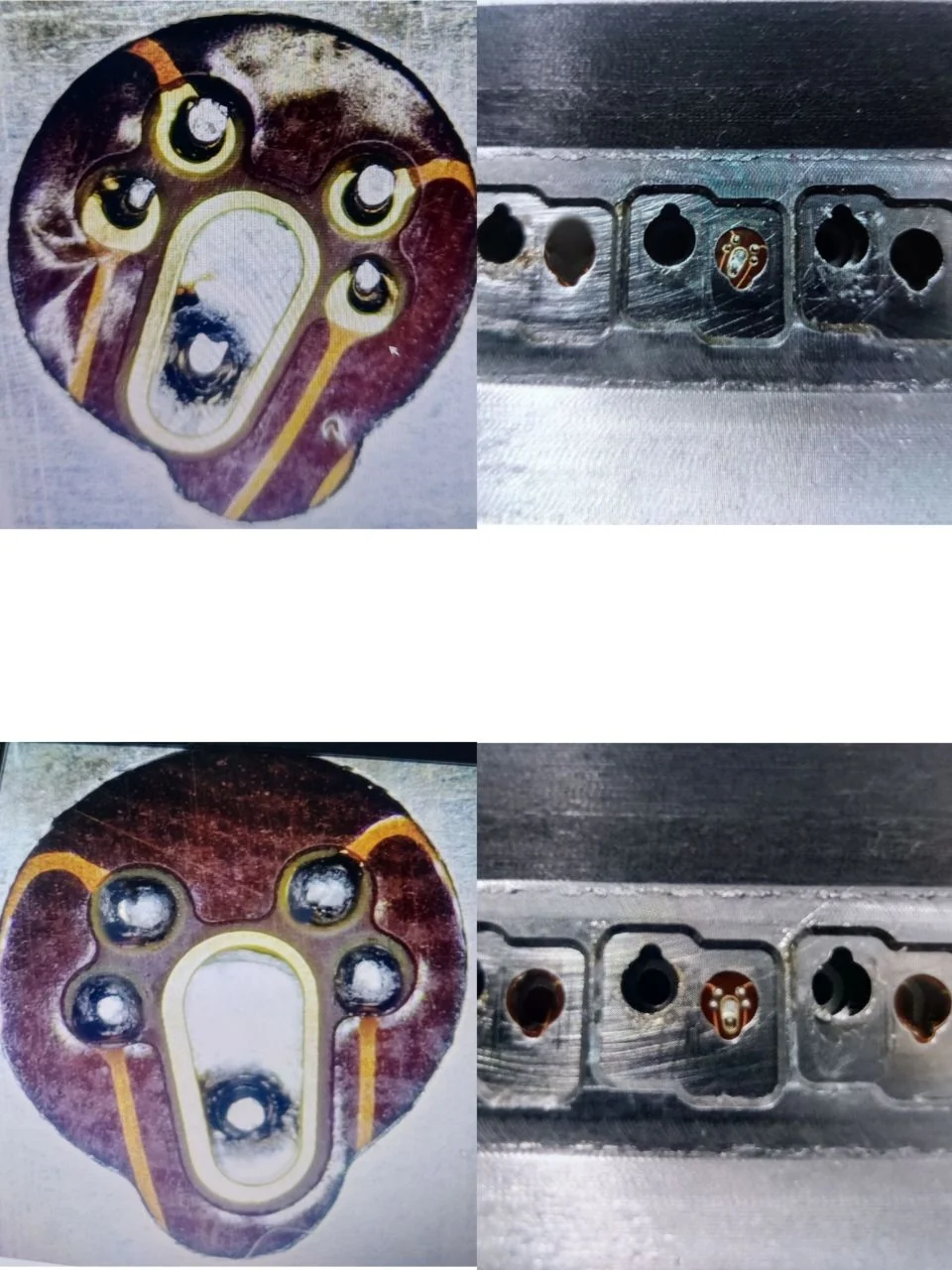
Supplied process and sample evidence supports the reading experience without being presented as an undocumented customer project.

01

A flexible circuit must be presented consistently

FPC work is not simply small-board soldering. The flexible substrate, bend area, local stiffness and pad position influence how the joint can be approached. An evaluation should establish the location that needs local support and the fixture surfaces that create a repeatable reference without over-constraining the part.
02

Pad geometry and local delivery

The pad dimensions, conductor finish, clearance around the joining area and desired solder-joint appearance frame the ball-diameter and nozzle-access discussion. Localised delivery can be considered when it fits the actual geometry, but the process has to be demonstrated on the intended FPC condition.

03

From development fixture to production flow

A compact development setup may be useful to assess support and positioning before any larger automation concept is selected. When a process is promising, handling, fixture repeatability, part change and inspection sequence should be evaluated as distinct production decisions.

Application development guide

Move from a component label to a defined process question

Flexible printed circuits require an evaluation that treats flatness, local support, bend zones and datum strategy as parts of the soldering process. A smaller pad is not the only challenge: the way a flexible part sits in the fixture determines whether the joint can be approached repeatedly.

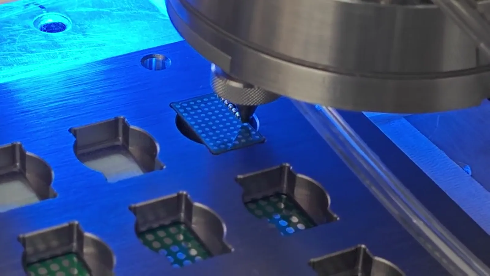
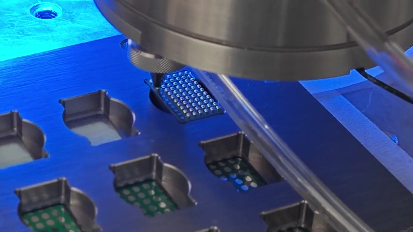
Supplied process frame showing precision soldering fixtures and multiple supported test positions
Supplied fixture/process context used to discuss local support and access. The component identity is not asserted.

Evidence-aware process context

Use real supplied visuals to frame the review, not to overstate the result

The visible process relationship is useful for discussing access, fixture support, motion and position reference. It does not prove a material, industry or qualification claim for an unlabelled sample. The final process path should follow the component information and a representative evaluation.

Prepare a sample evaluation →

05

Support the local soldering zone without over-constraining the circuit

The fixture should make the target area accessible while supporting the flexible substrate in a way that is relevant to the actual process. Review the local stiffness, nearby bend area, contact surfaces, component population and how the part is presented for loading. A fixture can also provide a mechanical datum, but the datum must represent the desired joint position. Without stable presentation, a programmed motion coordinate or an image reference cannot establish the same physical nozzle-to-pad relationship from one trial to the next.

06

Review ball, pad and path as one geometry

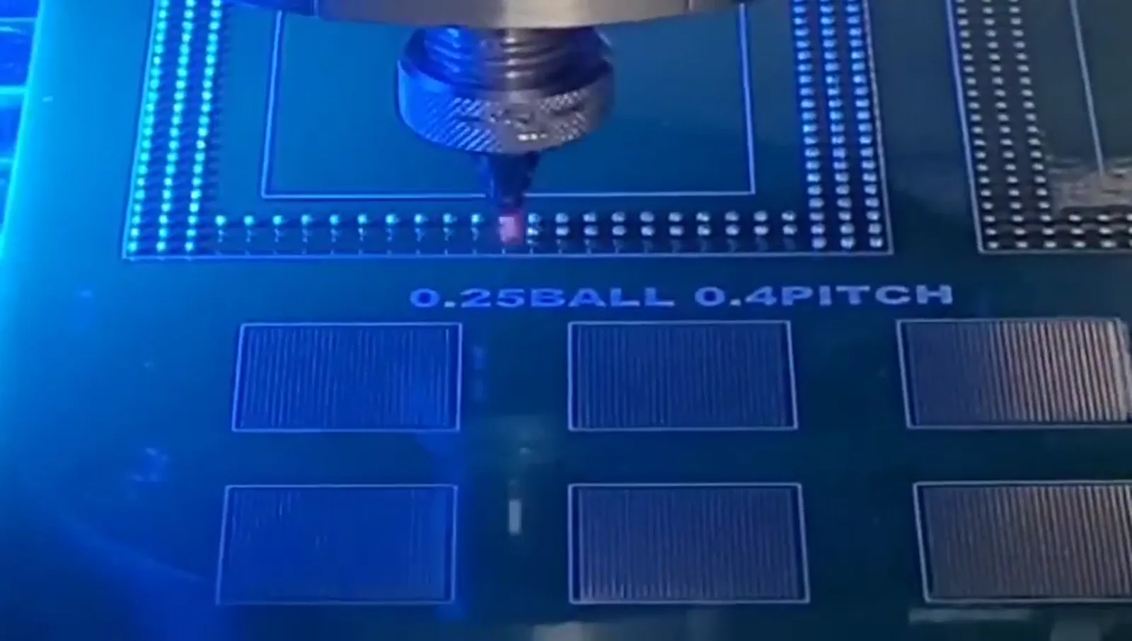
Ball diameter, pad dimensions, conductor finish, clearance and desired joint appearance should be documented together. Localized delivery may be considered if the guide/nozzle can reach the area with a practical path and the trial demonstrates a suitable result. The source-supported 0.25 mm ball / 0.4 mm pitch material is a test-pattern demonstration only; it does not define a universal FPC pitch or selection condition. Representative sample evidence remains the basis for a bounded conclusion.

07

Separate process feasibility from handling design

A sample process can confirm whether the local joint and fixture relationship warrant further work. It does not automatically solve the later production question of loading, flatness control, part change, inspection and handling. Once the local condition is understood, a configuration discussion can examine those additional requirements. This staged approach prevents a feasibility video or visible sample from being treated as a claim of universal FPC automation capability.

Useful inputs

Prepare the information that can make a process review specific

  • FPC images showing pad, bend and support areas
  • Conductor finish and pad details where available
  • Required part orientation and fixture constraints
  • Current process, joint sequence and acceptance criteria

What matters in evaluation

Process considerations for FPC

A feasibility review makes part-specific constraints explicit before automation is selected.

01

Fixture plan for flatness and repeatability

02

Ball diameter matched to joint geometry

03

Localized heat input assessment

04

Vision or fiducial strategy when required

Configuration path

Choose the system after the process

A desktop development system can help establish the process; automated handling should be considered only after the part support and positioning strategy are understood.

Explore custom automation

How to test

Prepare a useful sample evaluation

Include FPC photographs, layer / pad information if available, sample quantity, current method and the expected solder-point sequence.

View sample-testing process

Supplied sample evidence

Local processing, visible sample context

Sample photography supports technical discussion without attributing imagery to an undocumented customer or claiming mass-production results.

Real supplied sample imagery

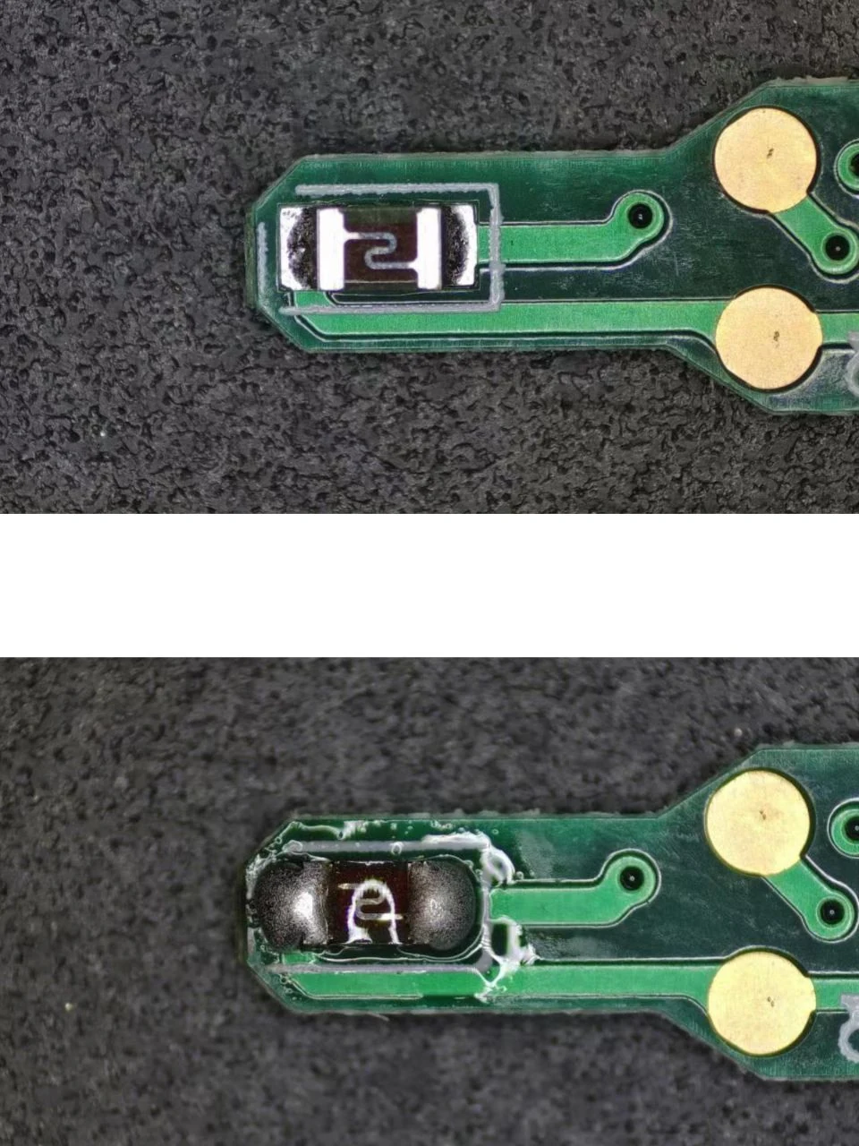
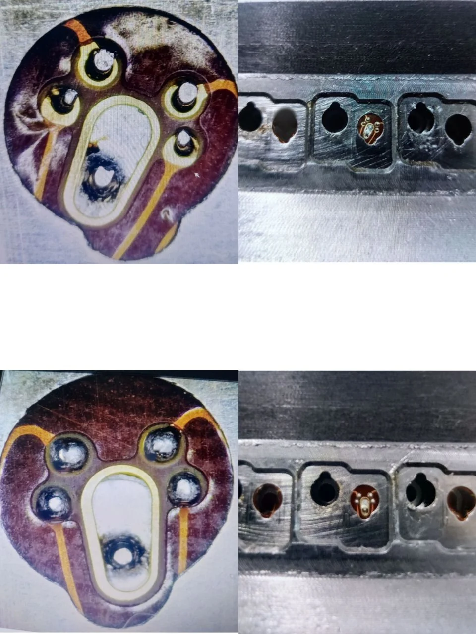
Sample solder joint before / after processing

Before / After
Sample solder joint before laser solder ball processing
Before soldering
Sample solder joint after laser solder ball processing
After laser solder ball processing

Real supplied images; visible appearance should be judged against the requirement for the actual component.

Have a micro-soldering application to evaluate?

Send the component information. Start with the process.

Share drawings, sample photographs or soldering requirements. The engineering discussion can connect the component to a suitable process and machine configuration.

WhatsApp Email