
Process overview
How Laser Solder Ball Jetting Works
The supplied technical information describes a process in which an individual solder ball enters a guide channel, is melted by laser energy at the nozzle and is jetted toward the soldering position using gas pressure. In a complete application, that core action is coordinated with positioning, workholding, fixture design and process programming.
Documented process relationship
From individual solder ball to localized joint
These restrained explanatory diagrams make the visible process sequence easier to read. They do not imply unverified dimensions, pressures or internal construction.

Educational process guide
The localized soldering event begins with a supported workpiece
The supplied technical information describes a process in which an individual solder ball enters a guide channel, is melted by laser energy at the nozzle and is jetted toward the soldering position using gas pressure. In a complete application, that core action is coordinated with positioning, workholding, fixture design and process programming.
The process starts with solder-ball feeding and individual-ball separation. Stable delivery is part of the process definition because solder volume, guide path and the relationship between the ball and nozzle need to be evaluated together.
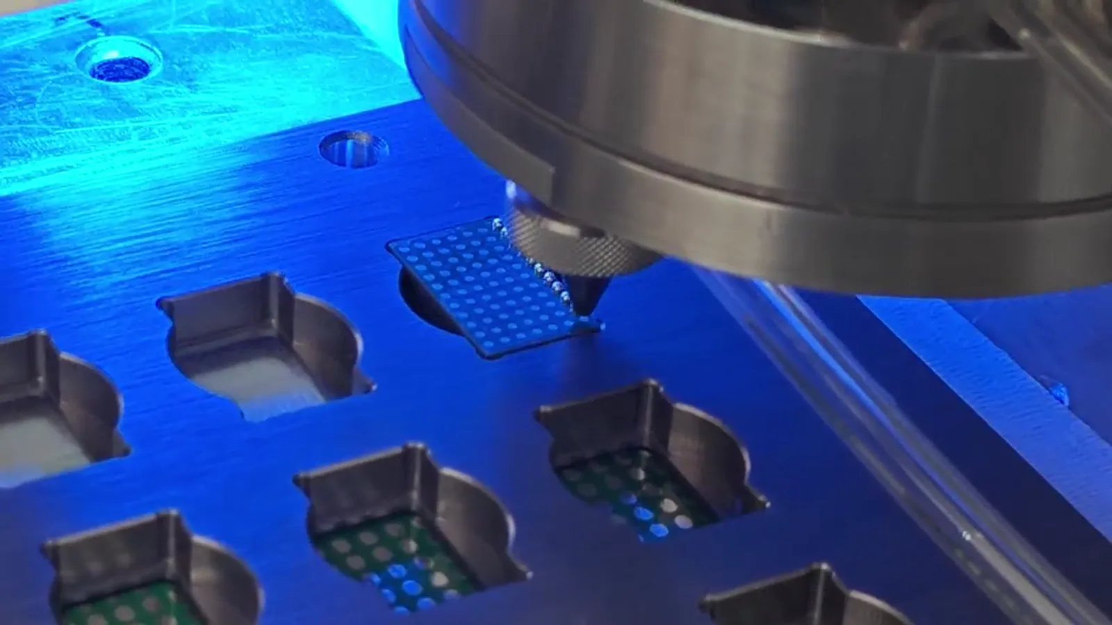
Step through the sequence
Each stage changes the relationship between material, energy and the part
The process reads as a linked sequence. The numbered spine keeps every step in live HTML while a large supplied frame anchors the physical workpiece relationship.
- 01
Solder-ball feeding
A controlled feed presents solder balls to the process head. Feed condition and the selected ball are evaluated with the intended joint rather than inherited from another application.
- 02
Individual-ball separation
One ball is isolated before the soldering event. This establishes the material input for the next cycle, but does not by itself establish a suitable joint volume or result.
- 03
Guide and nozzle relationship
The guide/capillary and nozzle must relate the ball to the laser and workpiece. Access, working distance and the fixture determine whether this relationship can be practical on the part.
- 04
Laser interaction and melting
Laser energy melts the ball at the nozzle. The required condition is selected around the component, solder material, heat path and target joint; a configuration reference is not a universal recipe.
- 05
Gas-assisted transfer
Gas assistance transfers molten solder toward the target. The path, stand-off relationship, adjacent features and surface condition all remain part of the process evaluation.
- 06
Joint formation and cooling
The delivered solder forms the joint on the selected workpiece. The visible result should be reviewed against the application’s own criteria rather than treated as a generic qualification.
- 07
Vision and motion control
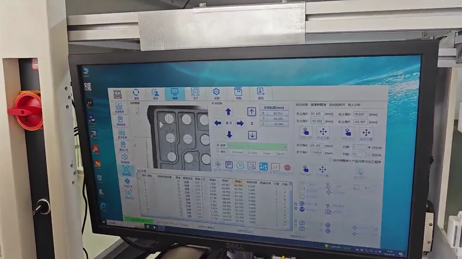
A stable fixture, mechanical datum and—where required—CCD reference connect the programmed coordinate to the physical jetting point. Calibration is part of the process, not an optional afterthought.
- 08
Inspection and next cycle
The complete sequence may include motion travel, multiple points, handling, inspection and the next programmed action. A documented maximum dot rate is not complete application cycle time.
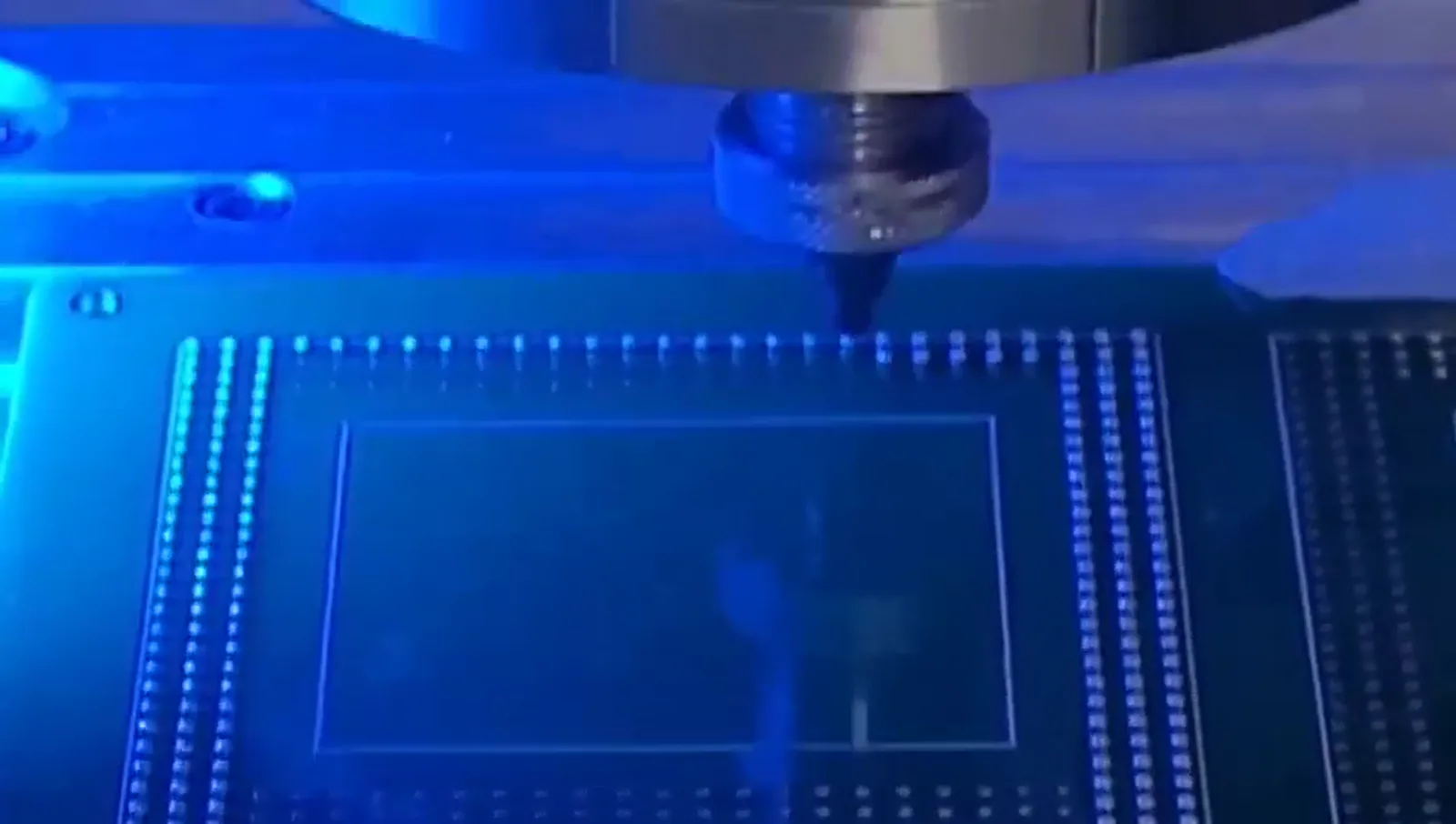
Process relationships
Technical explanation needs both the physical view and the system view
The photographs show supplied process context. The diagrams explain generic relationships and do not replace representative sample testing.
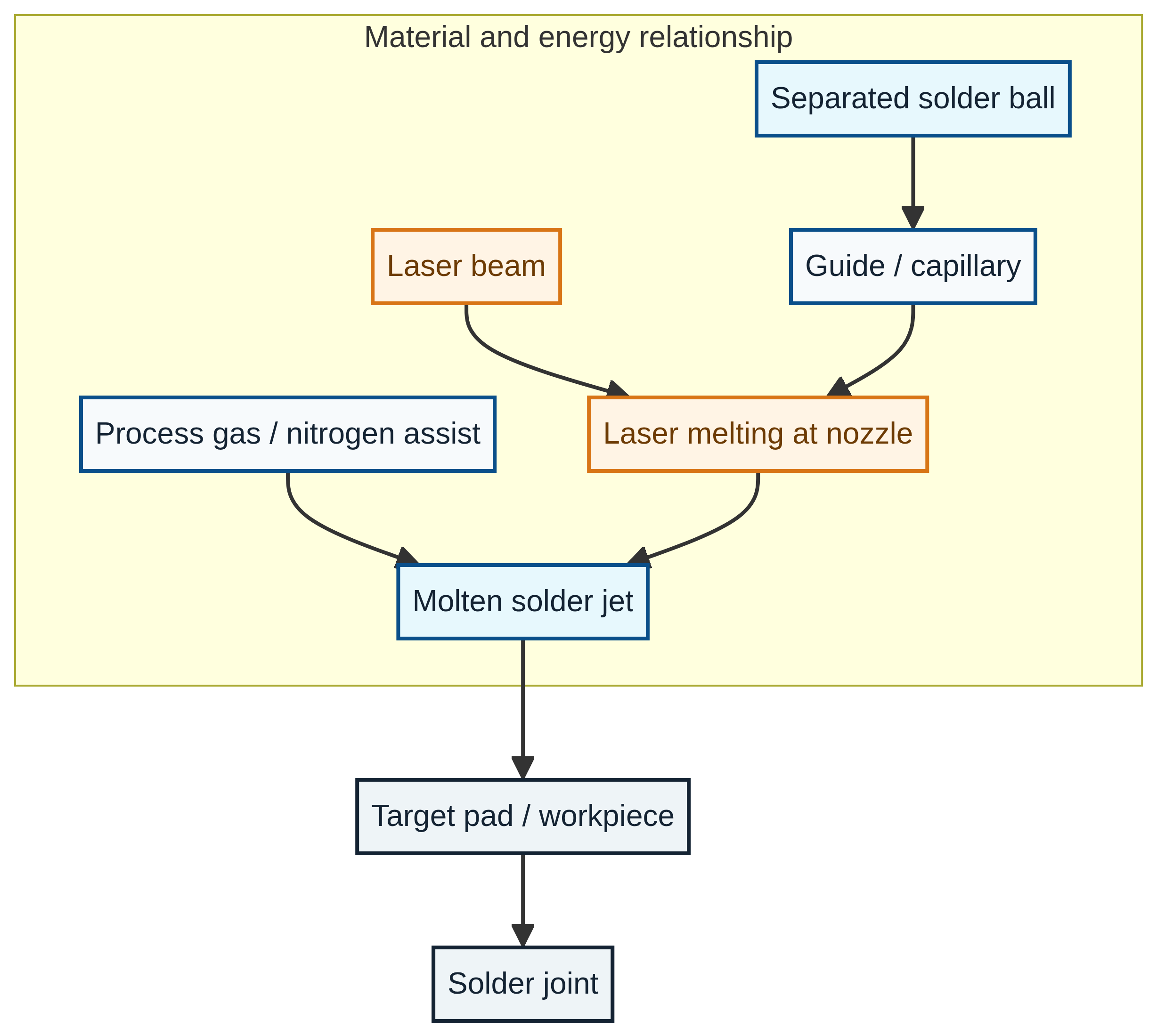
Explanatory cross-section: dimensions and internal machine construction are not claimed.
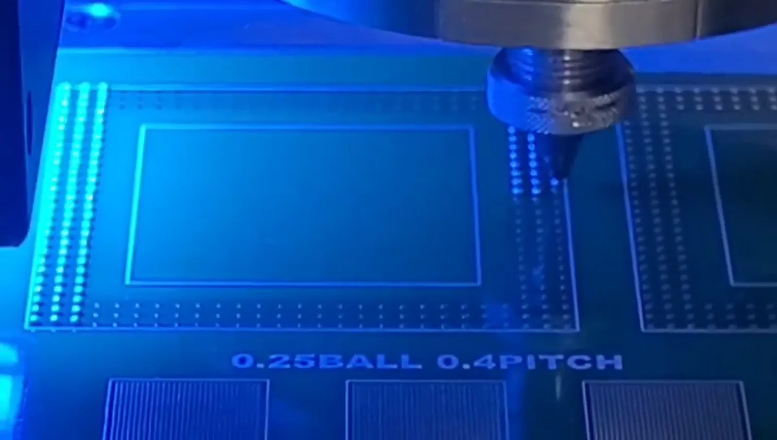
The 0.25 mm ball / 0.4 mm pitch marking is a supplied test-pattern demonstration only.
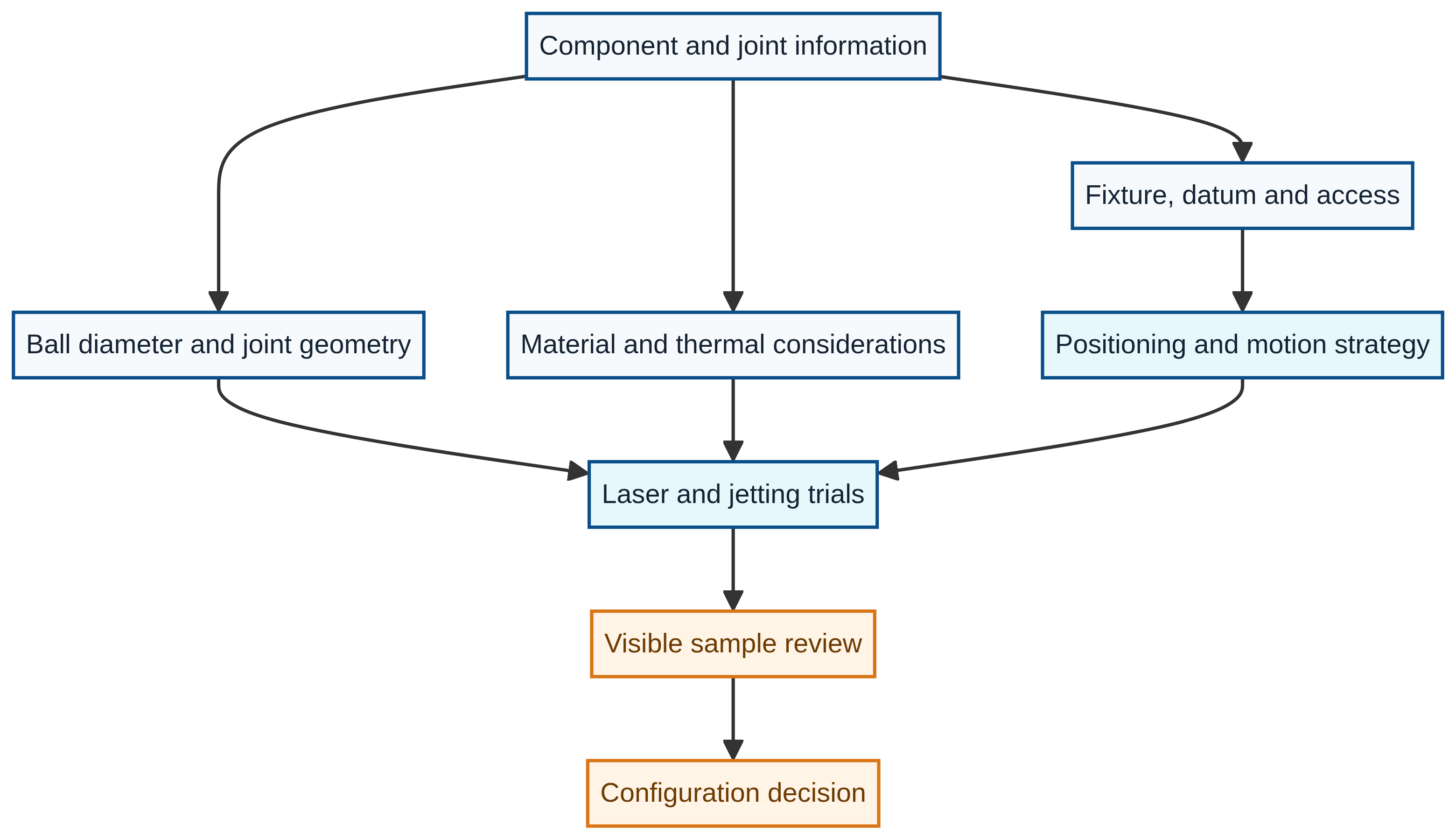
A practical evaluation links joint, fixture, access and selected process trial before a configuration is chosen.
Positioning and reference
Vision is one part of a stable reference chain
Laser energy is applied at the nozzle to melt the solder ball. The required energy setting belongs to the selected process and machine configuration; it should not be treated as a universal value across applications.
Motion, fixture references and—where appropriate—vision positioning bring the workpiece and process head into a defined relationship. Gas-assisted jetting transfers the molten solder to the intended location.
A useful production process connects ball delivery, laser control, motion, recipe logic, fixturing and inspection. Sample testing is the practical way to determine whether that sequence fits a particular electronic assembly.
Read the vision reference guide →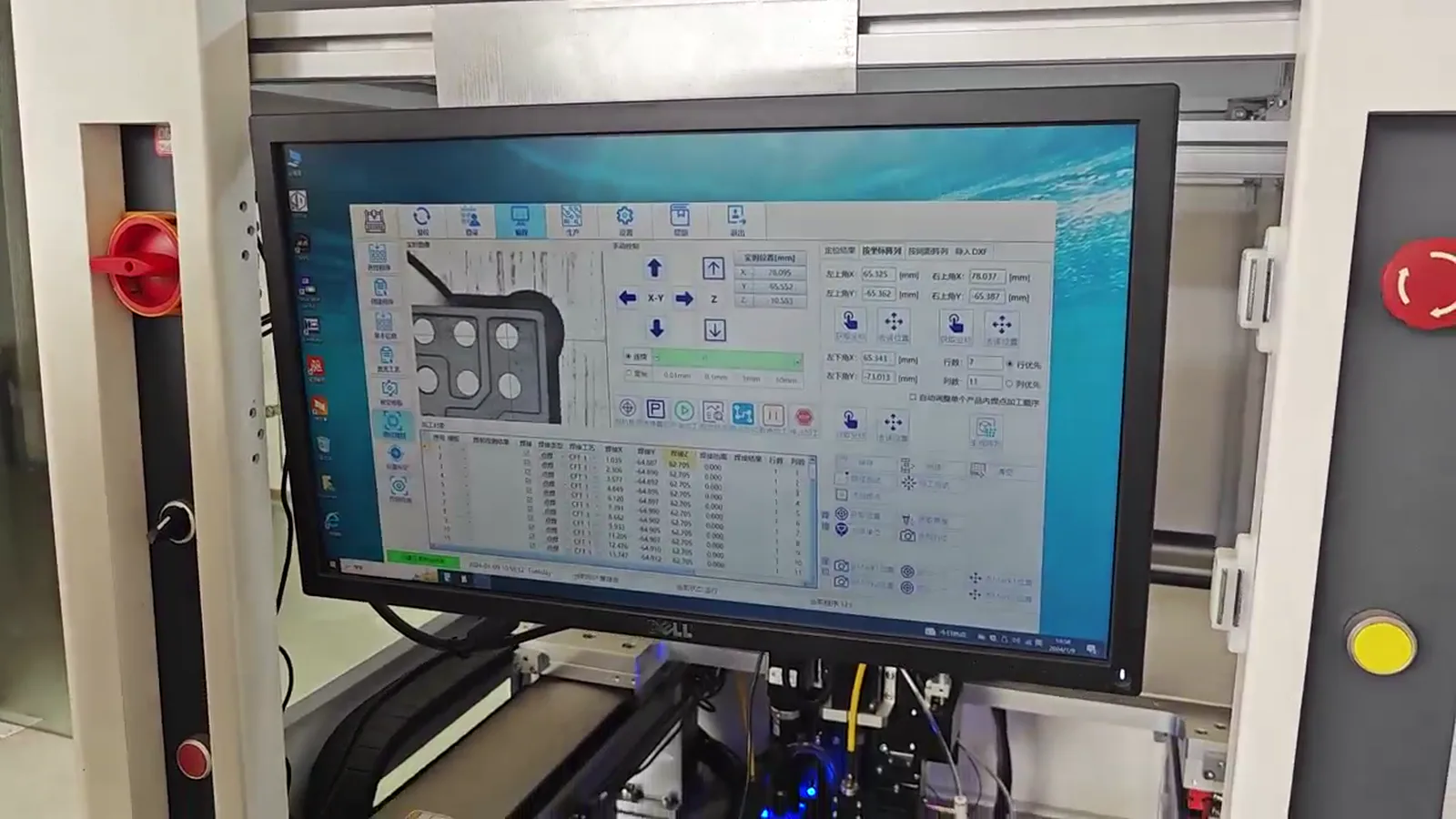
Authorized industry reference
A close-up visual reference for the localized jetting event
The approved external visual helps show the relationship between a process head, laser interaction and a solder-ball array. It is a contextual reference, not a Dayan product or a performance statement.
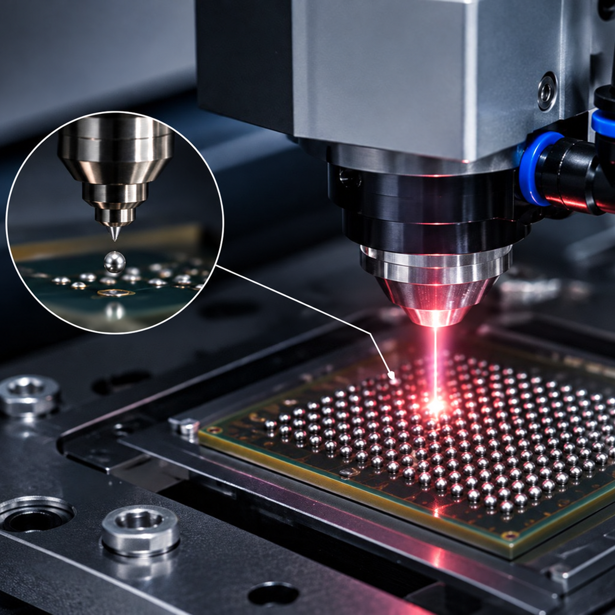
Authorized third-party process reference. Source branding and overlay text have been removed; it provides visual context only and is not a Dayan machine or performance claim.
What must be reviewed
Use the explanation to prepare a real sample review
Component geometry, fixture support and selected process conditions determine what the generic sequence means for an application. The final process scope should be based on representative evidence and customer-defined inspection criteria.
Have a micro-soldering application to evaluate?
Send the component information. Start with the process.
Share drawings, sample photographs or soldering requirements. The engineering discussion can connect the component to a suitable process and machine configuration.