
Potential precision-electronics application

Camera Module Laser Soldering

Camera-module work can involve small pads, limited access and assemblies where heat input must be considered carefully. Laser solder ball jetting may be evaluated as a localized process option when the joint design, materials and component handling support it.

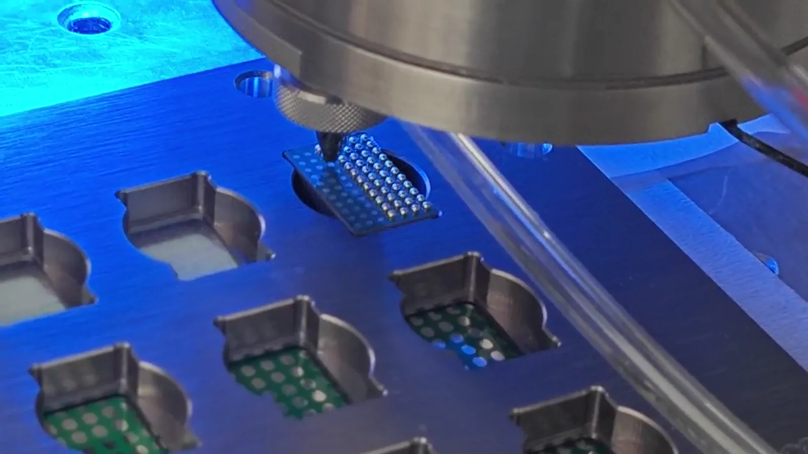
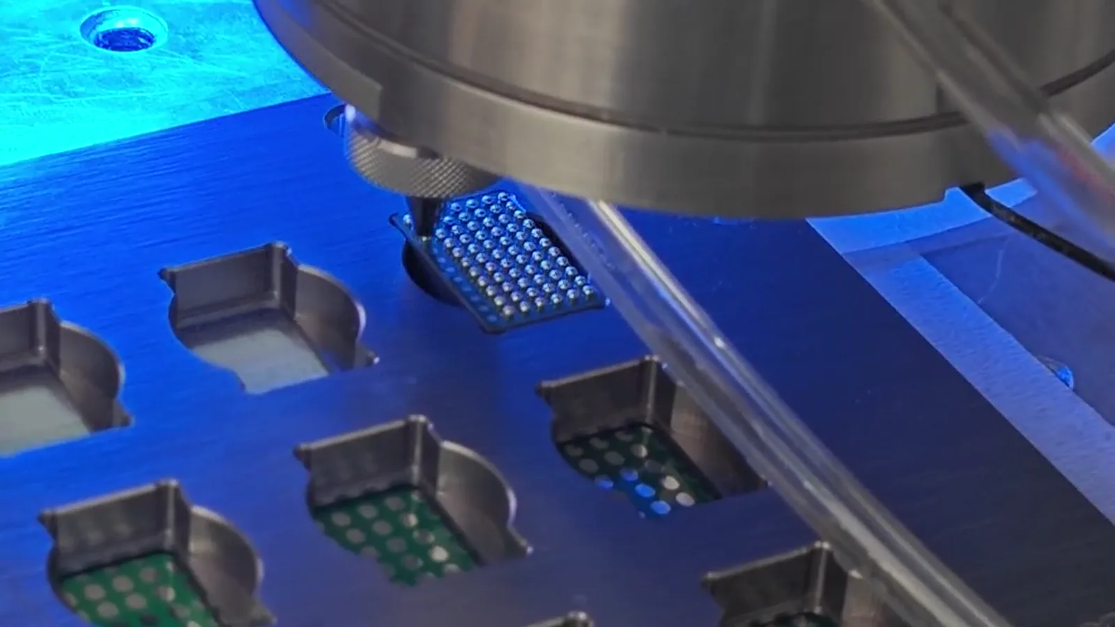
Supplied close-up of a jetting head over supported electronic test positions
Supplied process context for discussing compact joint access and fixture support; it is not an attributed camera-module customer case.

Application challenge

Start with the real assembly environment and working envelope

Camera assemblies often combine compact geometry with sensitive optical and mechanical elements. The engineering question is how to reach the intended joint without treating the entire assembly as a generic soldering target.

Typical evaluation looks at pad size, wire or terminal access, component datum, clearance around the joint and the relationship between the joint and adjacent features.

Camera assemblies often combine compact geometry with sensitive optical and mechanical features. The engineering question is how to reach the intended joint without treating the entire assembly as a generic soldering target.

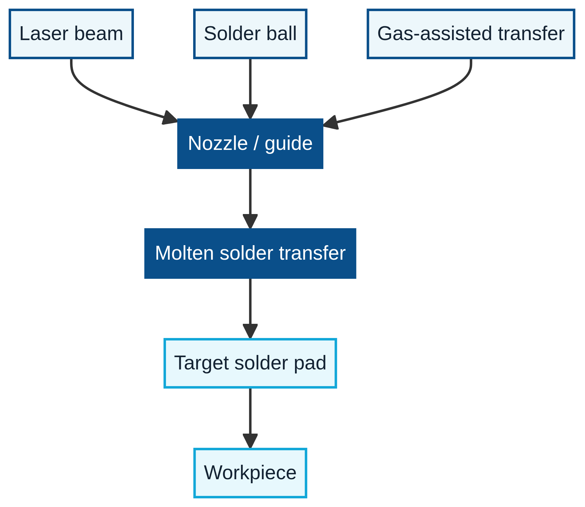
Diagram showing the relationship between the laser, solder ball, nozzle, gas-assisted transfer and supported workpiece
Generic nozzle-to-pad relationship without dimensions or a camera-module performance claim.

Camera-module assembly context

The visual story begins with support, access and the local process event

Supplied process and sample material supports the reading experience without being presented as an undocumented customer project. Each image is a technical context, not an application result.

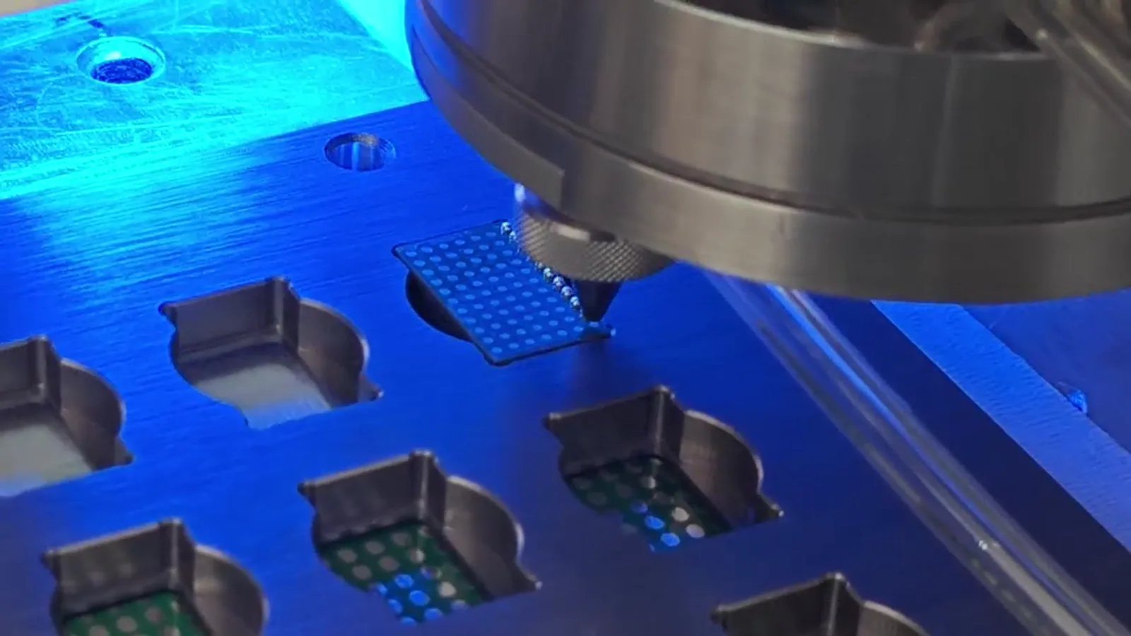
Supplied jetting head approaching a supported workpiece in a precision fixture

Process head and fixture

Nozzle access and support are seen in process context; the component identity is not asserted.

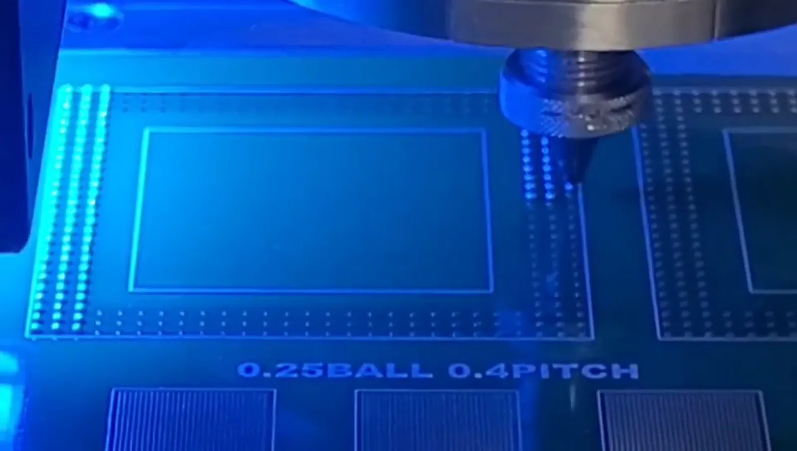
Supplied localized laser soldering frame above a fine-pitch test pattern

Localized process

The frame supports a process discussion. Its 0.25 mm ball / 0.4 mm pitch marking remains a test-pattern demonstration only.

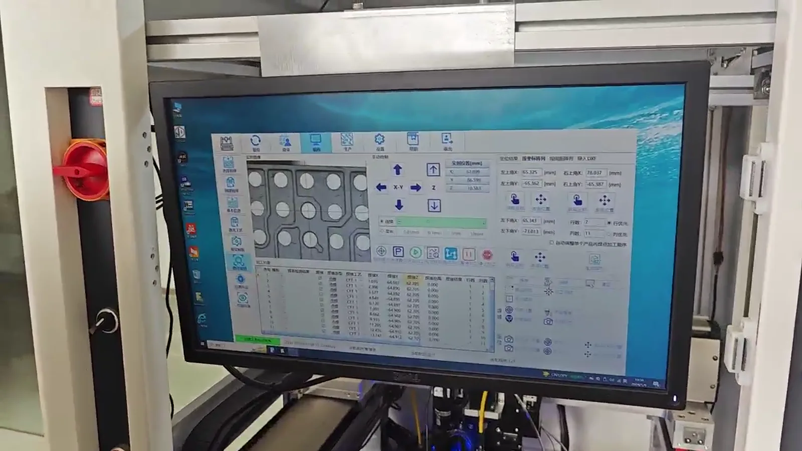
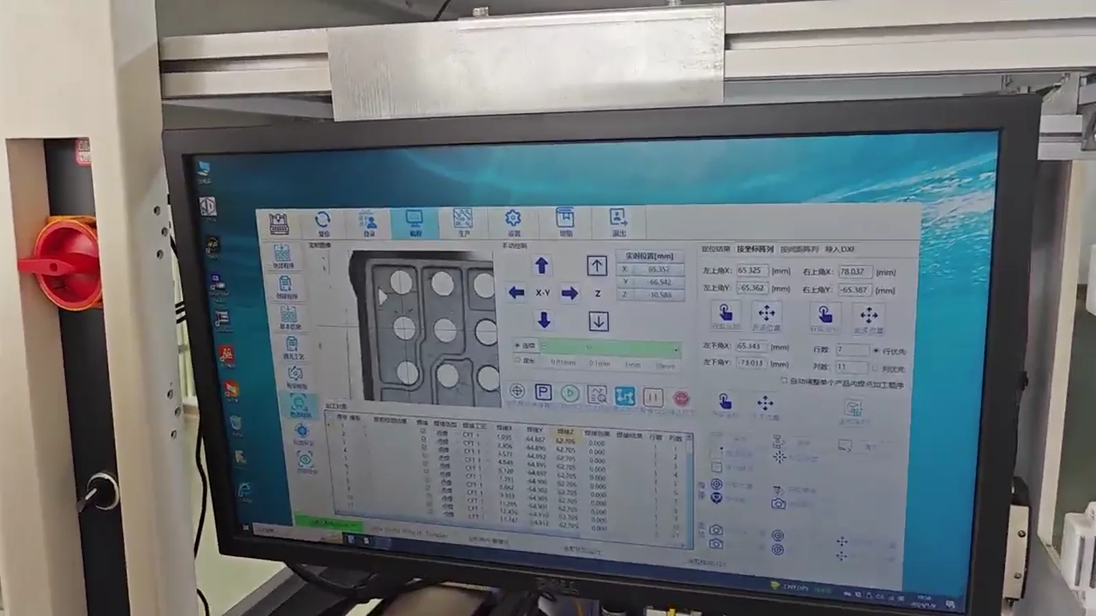
Supplied CCD positioning software interface in a precision soldering machine

Process interface

Machine-operation context for position reference; it is not proof of an application-specific software scope.

Application development guide

Move from a component label to defined process questions

The application review remains intentionally grounded in the actual terminal, pad, fixture and inspection requirement. The visual system exposes those relationships rather than hiding them inside equal cards.

  1. 01

    Start with the connection environment

    Camera-module assemblies can bring FPC terminations, terminals and compact mechanical or optical structures close to the soldering location. The evaluation begins by identifying the actual connection, its access direction and the components that must remain outside the working envelope. A technology label alone does not define whether a camera assembly is suitable.

  2. 02

    Joint position, heat and fixture support

    Small solder joints should be reviewed together with the mechanical datum, fixture support and the neighbouring heat-sensitive features. A fixture can stabilise presentation, protect nearby surfaces and provide a meaningful reference for a motion or vision routine. The required local process must be assessed against the real materials and customer acceptance criteria.

  3. 03

    When localized solder ball jetting may be evaluated

    A controlled solder-ball delivery and localized heat-input approach can be worth evaluating where the target joint is difficult to access with a broad process, or where solder volume and position must be considered closely. That is a sample-evaluation question, not a claim that one machine setting fits every camera module.

  4. 04

    Useful information for testing

    Close-up photographs of the terminal or FPC area, drawings where available, pad dimensions, the current joining method, expected joint sequence and the sample-inspection requirement create a better starting point. They allow the fixture, datum and possible vision strategy to be discussed alongside the soldering action.

Supplied CCD machine-operation frame around a fixture and precision soldering work area
CCD and fixture context helps discuss a reference chain; it does not demonstrate a camera-module result or customer configuration.

Application development guide

Move from a component label to a defined process question

Camera-module evaluation begins with the actual electrical connection and its relationship to nearby mechanical, flexible and optical features. Localized solder delivery may be worth investigating, but the test plan must define access, workholding, position reference and the customer’s own inspection requirement before a process conclusion is drawn.

Supplied close-up frame of a jetting head above supported electronic test positions
Supplied process context for discussing compact joint access and fixture support; it is not an attributed camera-module customer case.

Evidence-aware process context

Use real supplied visuals to frame the review, not to overstate the result

The visible process relationship is useful for discussing access, fixture support, motion and position reference. It does not prove a material, industry or qualification claim for an unlabelled sample. The final process path should follow the component information and a representative evaluation.

Prepare a sample evaluation →

05

Map the keep-out envelope around the joint

The target pad or terminal cannot be reviewed in isolation. Document nearby housings, flexible circuits, mechanical elements and any surface that must stay outside the physical working envelope. The fixture should support the assembly without changing the relationship between the joint and nozzle. A workable approach direction, component height and part orientation are often more informative than a broad description such as “camera module.” The right test arrangement exposes the selected joint while protecting and referencing the rest of the assembly.
06

Treat local heat as a component question

Laser energy is applied locally at the nozzle, but the real component still determines the thermal question. Material stack-up, pad finish, surface condition, adjacent features and fixture contact can affect the process response. A sample trial should record the selected ball, position reference, support arrangement and visible result against customer-defined criteria. It should not be re-described as a general camera qualification, production yield or a claim about an unrelated module.

07

Connect feasibility to the handling sequence

After a defined joint is evaluated, the scope can progress to loading, orientation, fixture changeover, vision checks, joint count and inspection. A standalone, dual-station or inline concept is selected around that sequence. Dot frequency alone does not provide a complete production answer because motion, vision, clamping, handling and review remain part of the usable cycle. The next step is a configuration discussion built on a documented sample condition.

Useful inputs

Prepare the information that can make a process review specific

  • Close-up joint and adjacent-feature images
  • Pad/terminal details and available drawings
  • Part datum and fixture or support constraints
  • Current process and customer-defined inspection criteria
Supplied process frame showing fixture-supported electronic test positions

What matters in evaluation

Keep the sample review attached to the actual component

A feasibility review makes part-specific constraints explicit before automation is selected. A fixture, part datum, access path and visible sample condition are part of the same conversation.

  • Fixture support to protect and reference the assembly
  • Controlled solder volume appropriate to the actual pad
  • Vision reference or repeatable mechanical datum
  • Thermal review around nearby sensitive features

Configuration and sample path

Choose the system after the process—not before it

A compact development platform or a fixture-based automation concept may be appropriate depending on sample volume, access and repeatability requirements.

Provide product photographs, pad dimensions, component drawings where available, present soldering method and sample acceptance requirements.

View the sample-testing process →
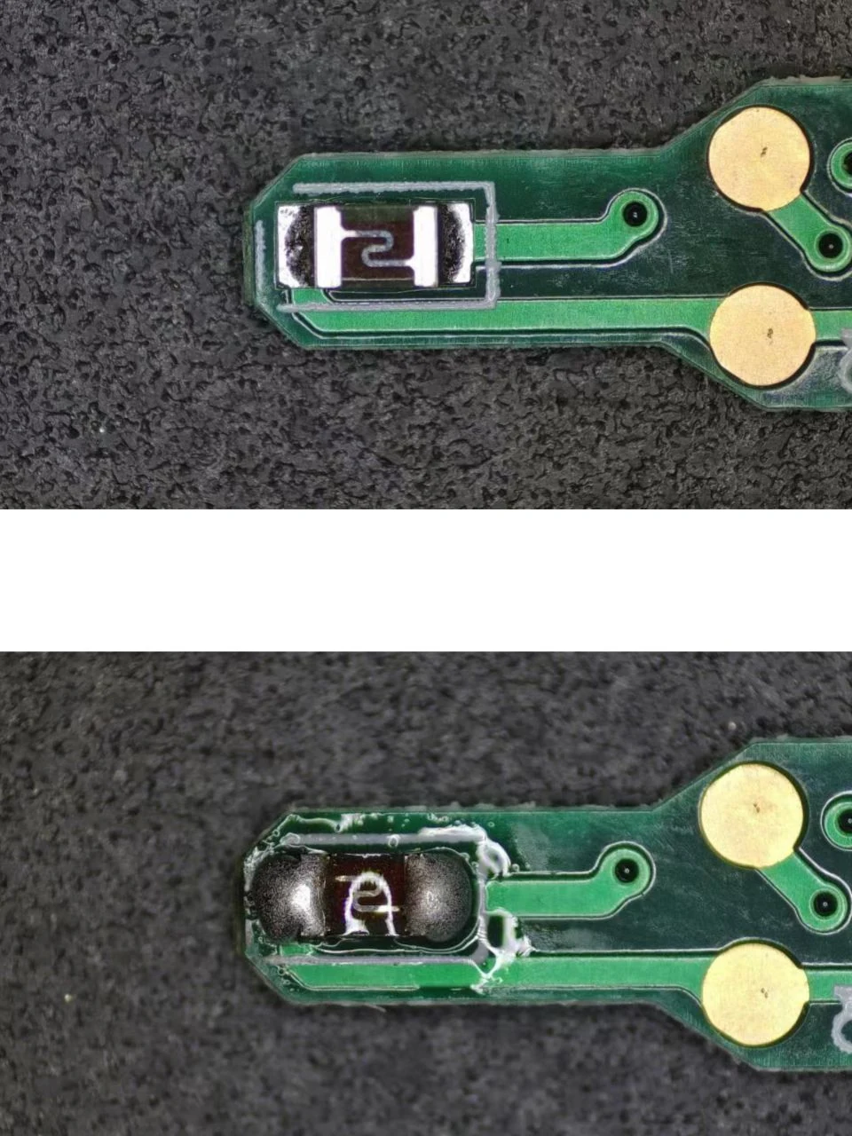
Supplied precision electronic component sample used for localized soldering process discussion
Supplied component sample imagery for process discussion. Component identity, material and qualification are not asserted.

Have a micro-soldering application to evaluate?

Send the component information. Start with the process.

Share drawings, sample photographs or soldering requirements. The engineering discussion can connect the component to a suitable process and machine configuration.

WhatsApp Email