Supplied sample imagery

Real Laser Soldering Samples

The supplied sample imagery is used as evidence of actual process work. Captions describe visible processing context and do not imply customer identity, production qualification or undocumented performance results.

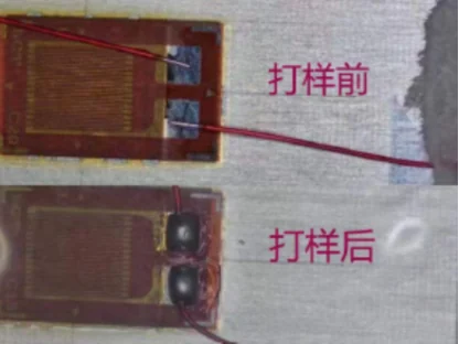
Before and after

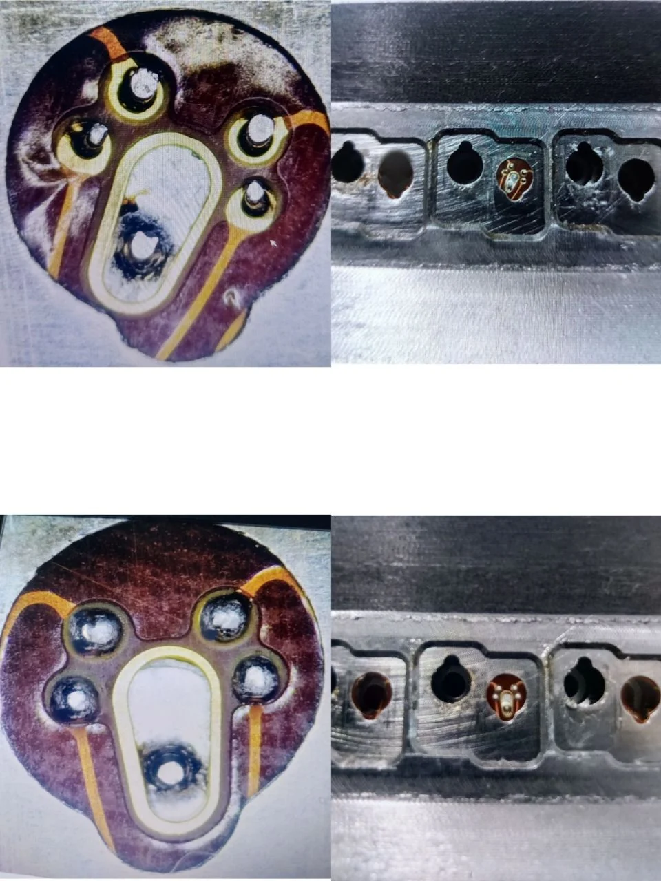
Comparison photography can show the target area before processing and the joint appearance after localized laser soldering.

Joint geometry

Solder-joint appearance is evaluated in the context of the component, pad geometry and the agreed process objective.

Customer sample evaluation

A customer sample can be reviewed according to its own drawings, quality criteria and process requirements.

Scope of evidence

Visual samples are valuable for discussion; they are not a substitute for a customer-defined inspection or qualification programme.
How to read the sample library

Visual evidence is useful when its scope remains explicit

Sample imagery can show a process context, a before/after relationship, a visible joint appearance or a test pattern. It cannot by itself establish customer identity, product sector, material composition, final inspection result, production yield or qualification. The library therefore identifies what is documented and retains unknown fields where the source does not provide them.

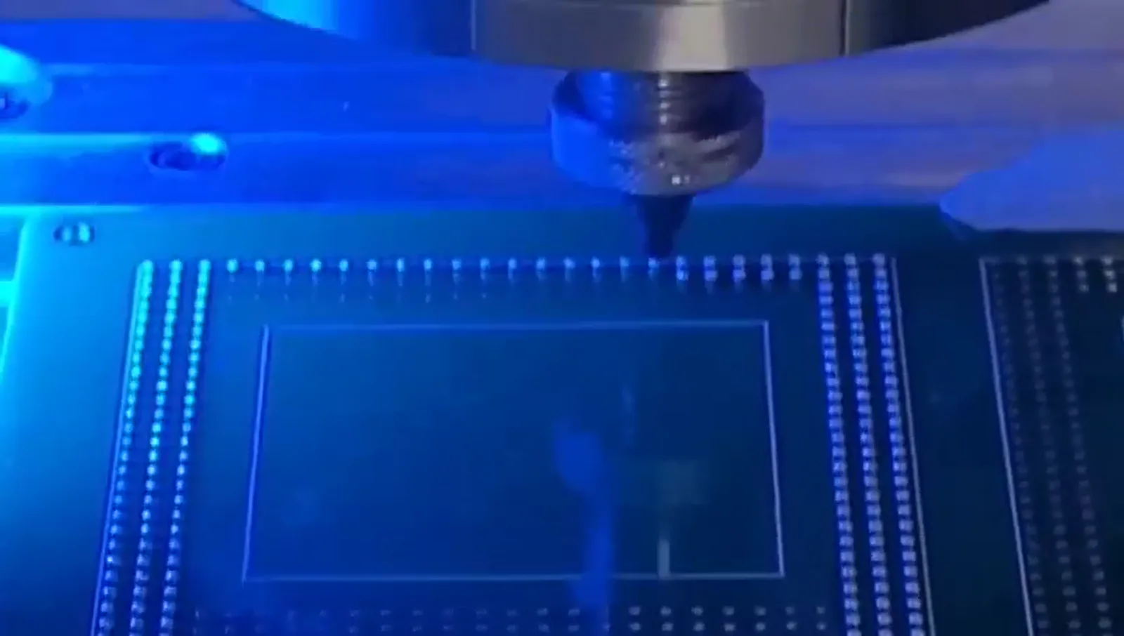
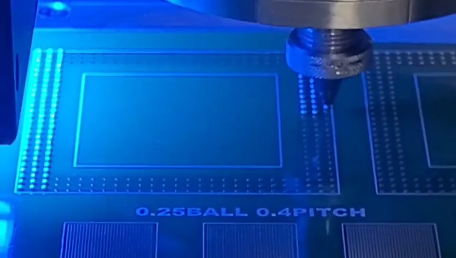
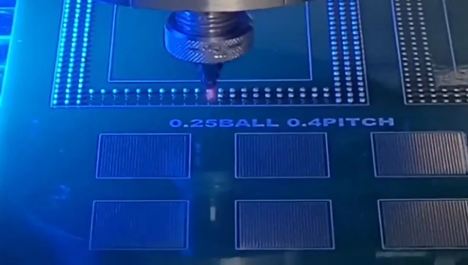
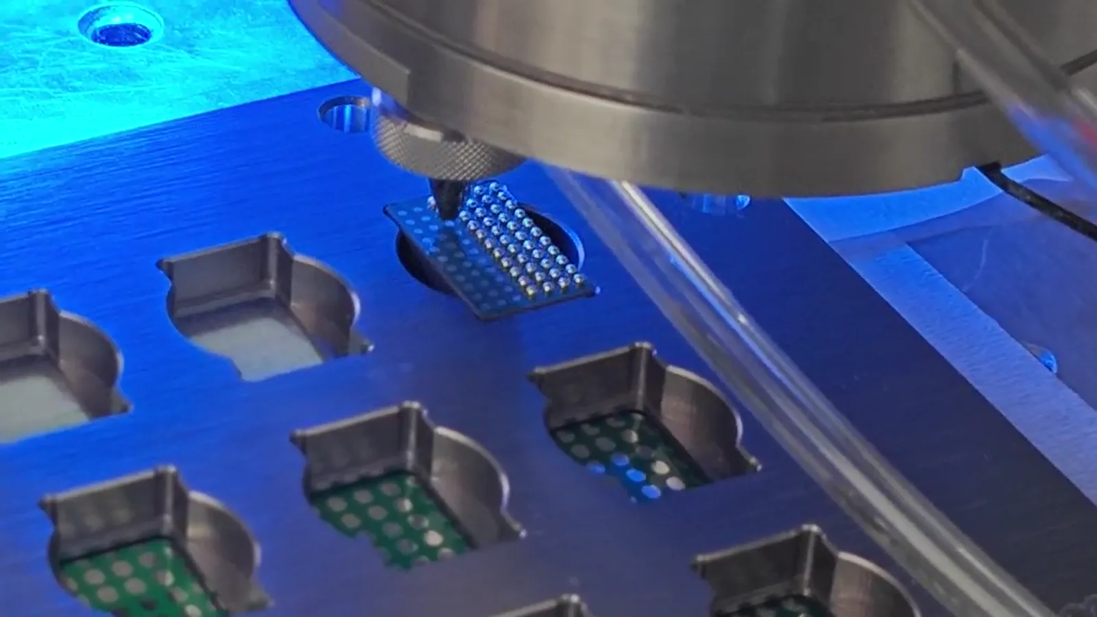
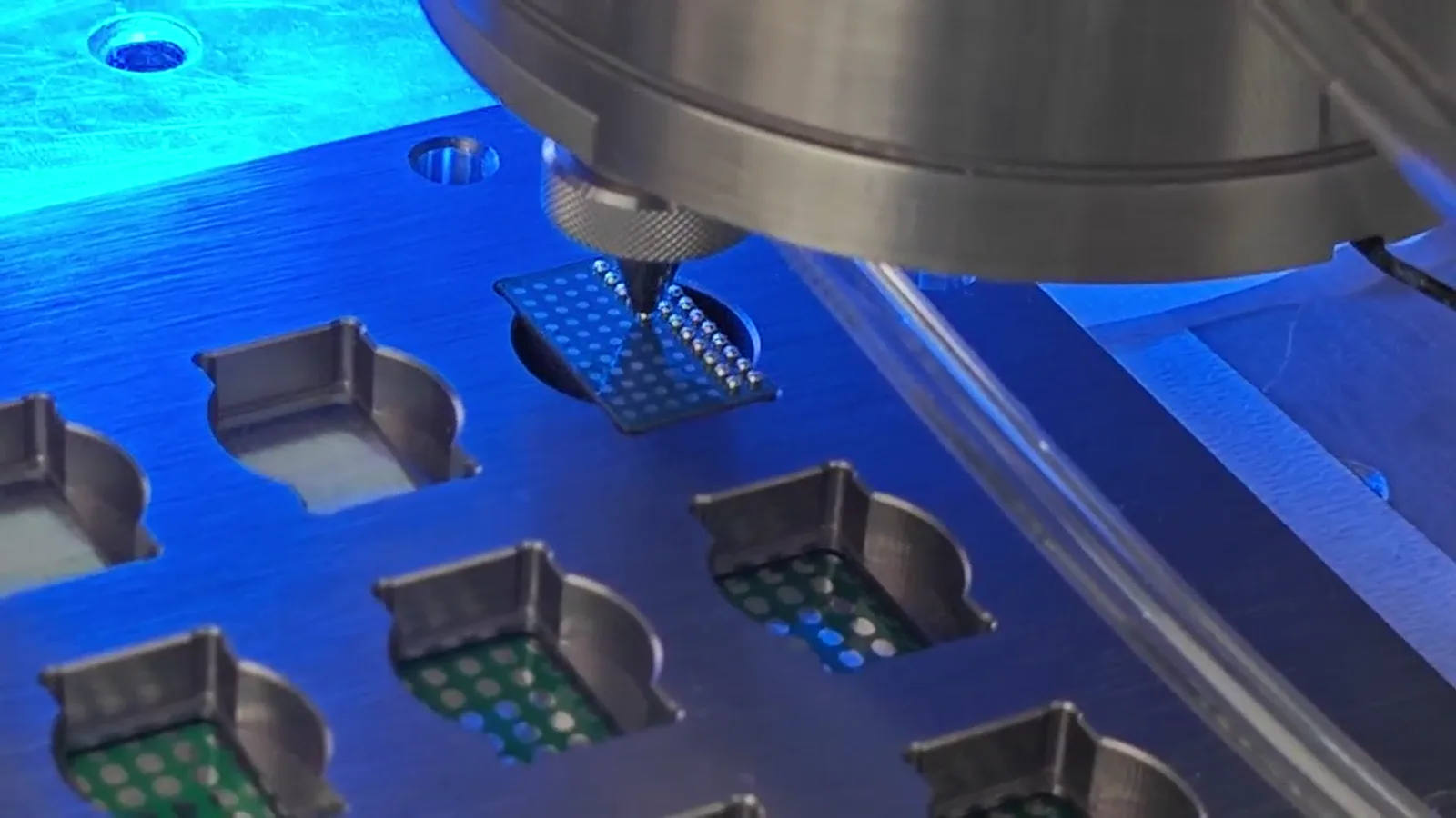
The supplied 0.25 mm ball / 0.4 mm pitch material is captioned as a test-pattern demonstration only. Other supplied component and joint imagery is presented as application-specific sample evidence rather than attributed to a named Camera, VCM, FPC, sensor, MEMS or connector customer project. This approach makes the evidence useful without turning it into a false case study.

Evidence categories

Process, fixture, joint and positioning context

These additional source frames help show how the process and workpiece relationship are discussed during engineering evaluation.

From sample image to engineering evidence

What makes a sample review actionable

  1. 01

    Define the component, target joint and available drawings.

  2. 02

    Record the pad/terminal, access, fixture and datum information.

  3. 03

    Select trial conditions around the representative workpiece.

  4. 04

    Review visible result against customer-defined criteria.

  5. 05

    Separate tested findings from unvalidated production conclusions.

Laser soldering sample library

Laser Soldering Sample & Process Library

Known details are listed directly. Where an application, material, joint type, ball size or pitch is not documented, it remains unknown rather than being inferred from the photograph.

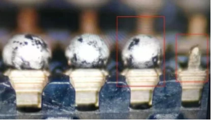
Supplied video frame of solder ball processing on a test pattern marked 0.25 ball 0.4 pitch

Fine-pitch test pattern

Application
Application-specific sample evaluation
Solder ball diameter
0.25 mm demonstrated in supplied footage
Pitch
0.4 mm demonstrated in supplied footage
Process note
Demonstration frame only; not a universal machine specification.
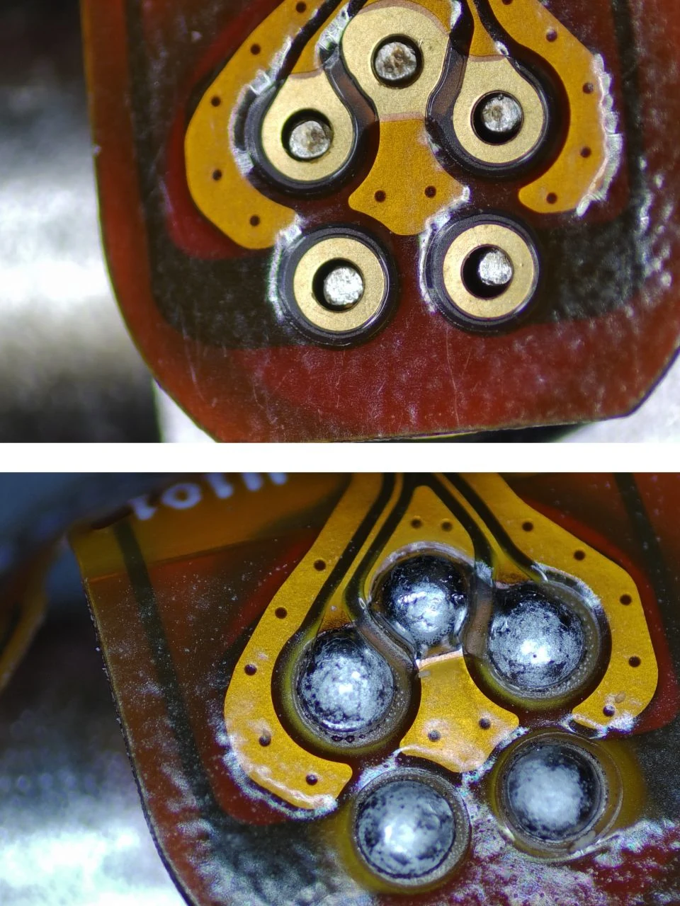
Supplied macro sample image showing solder joint appearance before and after processing

Localized electronic joint

Application
Application-specific sample evaluation
Joint type
Unknown
Material
Unknown
Process note
Supplied macro sample imagery used for joint-appearance discussion.
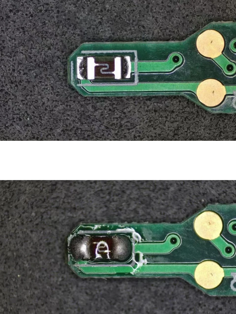
Supplied precision electronic component shown before and after localized soldering

Component sample

Application
Application-specific sample evaluation
Solder ball diameter
Unknown
Pitch
Unknown
Process note
Before/after component sample; component identity is not asserted.
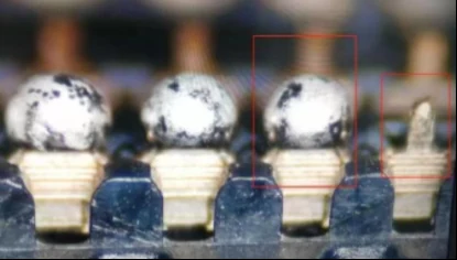
Supplied close-up macro image of a solder joint

Solder-joint appearance

Application
Application-specific sample evaluation
Joint type
Unknown
Material
Unknown
Process note
Visible appearance alone is not a complete inspection or qualification result.
Supplied process frame showing fixture-supported electronic test positions during solder ball jetting context

Fixture-supported process context

Application
Unknown
Joint type
Unknown
Fixture
Visible support positions in supplied process footage
Process note
Process context only; it does not identify a customer product.
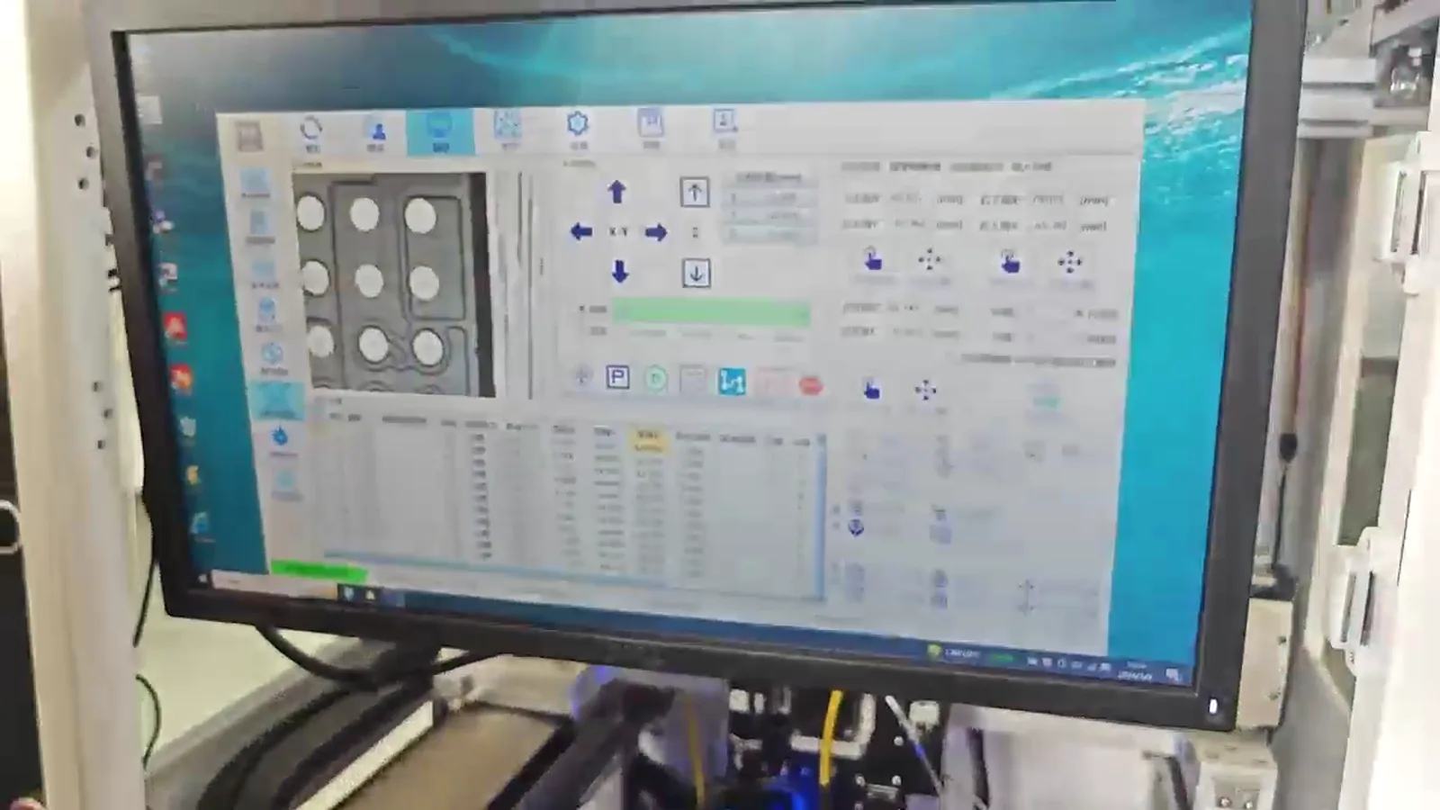
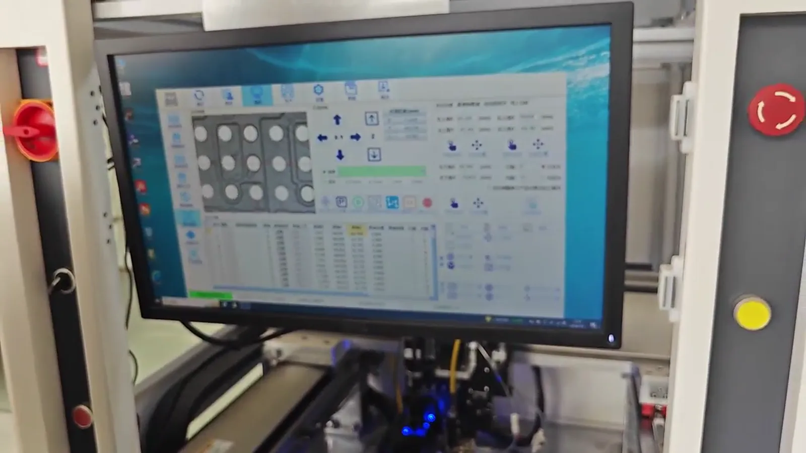
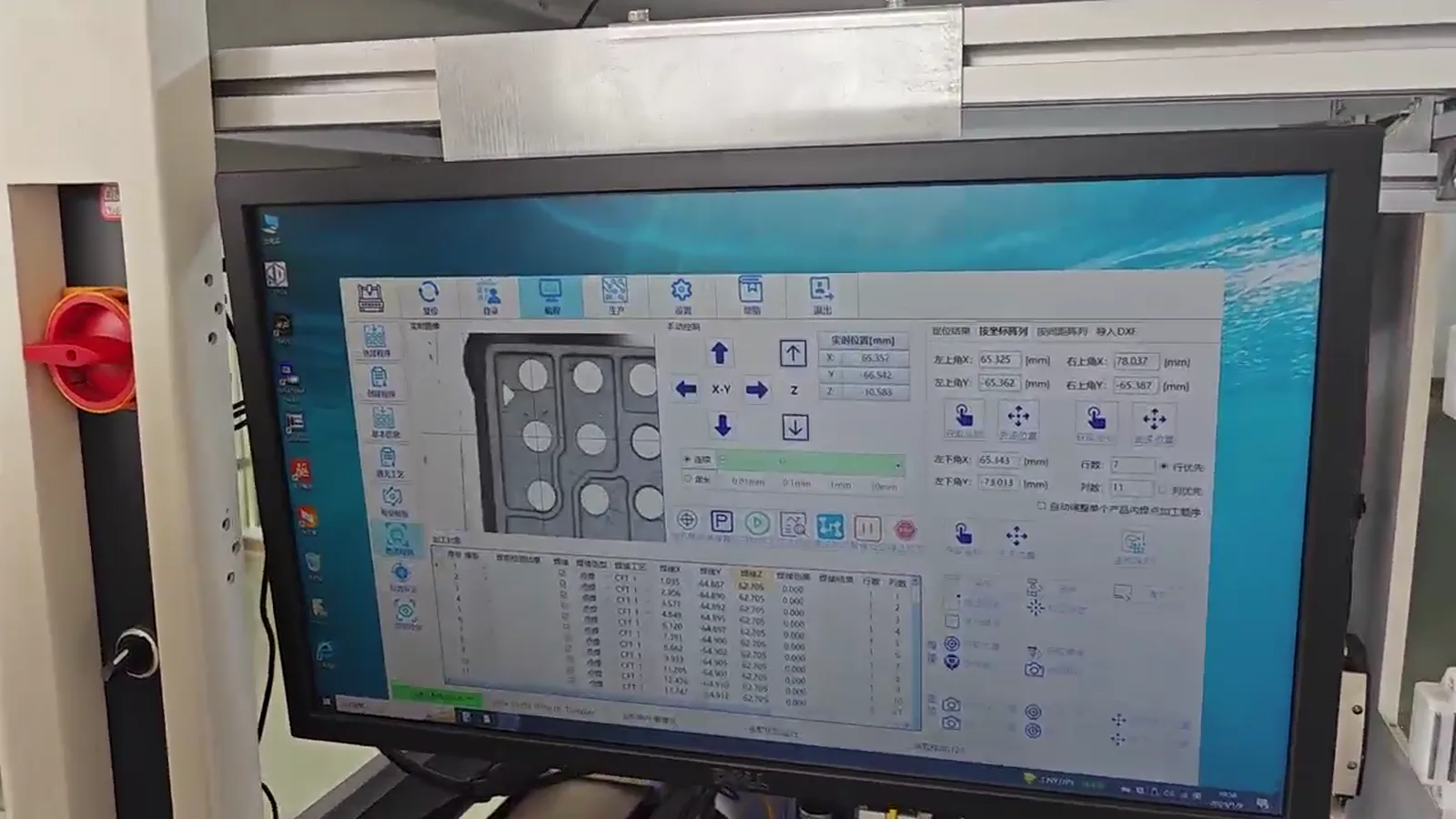
Supplied CCD machine-operation frame showing a precision soldering work area

CCD and work-area context

Application
Unknown
Position reference
CCD/machine-operation context visible
Material
Unknown
Process note
Final camera, recipe and fixture configuration remain application dependent.
Supplied localized laser soldering frame above a test pattern marked 0.25 ball 0.4 pitch

Localized test-pattern context

Application
Test pattern
Solder ball diameter
0.25 mm demonstrated in supplied footage
Pitch
0.4 mm demonstrated in supplied footage
Process note
Demonstration only; not a universal minimum pitch or production claim.
Supplied process frame showing an array-oriented localized soldering sequence

Array-sequence context

Application
Unknown
Joint type
Unknown
Process sequence
Repeated-array context visible
Process note
Cycle time and suitability require application-specific evaluation.
Supplied CCD machine-operation frame around a fixture and precision soldering work area

Camera / VCM context

Application
Camera / VCM context only
Component identity
Unknown
Position reference
CCD / fixture context visible
Process note
Not a named customer camera or VCM sample; requires component-specific validation.
Supplied process frame showing fixture-supported test positions during localized soldering

FPC support context

Application
FPC context only
Substrate / material
Unknown
Fixture
Supported process positions visible
Process note
Not an identified FPC sample; support, flatness and pad geometry require evaluation.
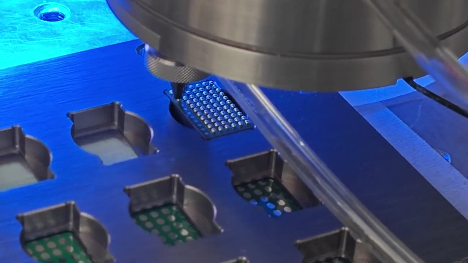
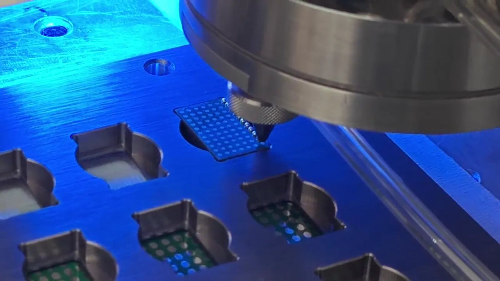
Supplied close-up process frame of a jetting head above compact supported test positions

Small-pad / confined-area context

Application
Small-pad / confined-area context only
Pad geometry
Unknown
Solder ball diameter
Unknown
Process note
Local access is visible process context, not a declared component capability.
Supplied process frame of a jetting nozzle over an array-oriented test context

Connector / terminal context

Application
Connector / terminal context only
Terminal geometry
Unknown
Joint count
Unknown
Process note
Not an identified connector sample; access and sequence remain application dependent.
Supplied precision electronic component shown before and after localized soldering

Microelectronic component context

Application
Microelectronic component context only
Component identity
Unknown
Pitch
Unknown
Process note
Before/after component imagery is evidence for discussion, not a qualification claim.

Real supplied sample imagery

Sample soldering comparison

Before / After
Sample area before soldering
Before soldering
Solder-joint appearance after processing
After laser solder ball processing

Supplied sample imagery used for process discussion.

Real supplied sample imagery

Localized joint processing

Before / After
Laser solder joint before processing
Before soldering
Laser solder joint after processing
After laser solder ball processing

Visible sample result; no undocumented test result is claimed.

Have a micro-soldering application to evaluate?

Send the component information. Start with the process.

Share drawings, sample photographs or soldering requirements. The engineering discussion can connect the component to a suitable process and machine configuration.

WhatsApp Email