
Begin with the defined workpiece position
The first question is not which diameter has been used elsewhere. It is where the molten solder must be transferred on this workpiece and how that location is defined. Record the intended soldering position, the local joint layout, the surrounding access available to the process head, and the way the part is presented. This creates a process description that is specific enough to discuss a candidate ball. It also keeps a ball-size conversation from becoming disconnected from the physical joint it is meant to serve. The supplied process description ends with transfer toward a defined workpiece position; it does not establish a diameter-to-joint rule for all products. For that reason, use the part’s own information and the customer’s stated requirements to frame the initial selection. If the target position cannot be presented consistently, a nominal ball diameter alone cannot resolve the process question. The review should instead return to workholding, the part datum and the nozzle approach before interpreting a test result as a basis for a final configuration.
Treat ball diameter as a candidate input, not a machine rating
An individual ball is the solder input for one documented jetting cycle, so its diameter is a meaningful process input. It should nevertheless be described as a candidate for evaluation, rather than as a universal setting or a shorthand for process suitability. The supplied technical information shows approximately 0.2–0.9 mm ball application for a documented configuration. This is useful bounded information, but it is not a universal machine limit, a recommendation for every workpiece, or evidence that every size in that range is appropriate for a particular joint. A sound review identifies the candidate diameter alongside the actual intended position and asks whether the complete process arrangement can be evaluated on representative parts. This wording is deliberately narrower than a capability claim. It preserves the distinction between a documented configuration and the configuration that may eventually be selected for a customer application. Where more than one candidate is under consideration, each should be recorded as a separate evaluation condition, with its own fixture, position reference and agreed assessment method.
Keep feeding, melting and transfer in the same selection discussion
Laser jetting is not simply a stationary ball placed on a workpiece. The documented process begins with feeding and individual-ball separation. Laser energy then melts the ball at the nozzle, and gas-assisted transfer moves the molten solder toward the defined workpiece position. Diameter selection belongs inside that full sequence. It is not sufficient to consider a ball only before it reaches the nozzle or only after a visible result is observed. The engineering review should identify the proposed ball as the input to the documented feed, melt and transfer steps, then assess that condition in the intended process arrangement. This avoids assigning an unexplained result to the ball diameter when the reference, fixture or motion relationship may also need attention. The supplied information does not provide a universal set of process settings for a diameter. It also does not establish material compatibility, joint metallurgy or production qualification from a video frame or sample image. The appropriate conclusion remains limited: a candidate diameter has been evaluated in a defined setup against the customer’s acceptance criteria.
Build the position reference before interpreting the ball choice
A useful diameter evaluation starts with a workpiece that is held and referenced in a repeatable, understandable way. Fixture, motion and datum must be reviewed together because each helps establish the relationship between the nozzle and the intended workpiece position. Where the application calls for it, vision may be included as part of that relationship rather than treated as an independent answer. The supplied documentation cites ±10 μm vision positioning for one described system. It must remain tied to that system and its conditions; it is not a universal accuracy statement for every fixture, part or setup. In practical evaluation terms, the team should identify the fixture support, the chosen datum, the programmed motion relationship and any vision reference before deciding that a ball candidate has been judged fairly. If any of those conditions changes, the prior sample observation may no longer describe the new arrangement. This integrated view is especially important when comparing candidate diameters, because a comparison is only useful when the workpiece position and reference strategy are understood for each condition.
Use the fine-pitch demonstration only for what it shows
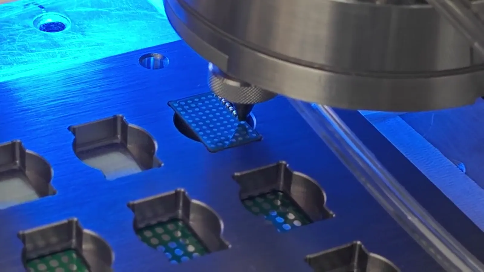
The supplied process material contains a frame demonstrating 0.25 mm solder ball processing on a 0.4 mm pitch test pattern. That is a specific and useful reference point, but its meaning should stay exact. It documents that demonstration only. It does not establish a minimum ball diameter, a minimum pitch, a production result, or a promise for a different joint layout. It should not be extended into a claim about another customer’s workpiece or used to bypass sample validation. When a proposed application appears visually similar, the right next step is to compare the actual workpiece position, fixture approach, datum and acceptance criteria with the test arrangement, then evaluate a representative sample. The same restraint applies at the other end of the documented range: approximately 0.2–0.9 mm ball application is configuration-specific information, not an automatic selection chart. A careful article or proposal can cite the demonstration as process context while making clear that the customer’s part requires its own evaluation. This keeps evidence and inference separate.
Separate documented configuration values from complete process planning
Several supplied values can help set the scope of a technical conversation, but none should be combined into a universal production specification. The documented information includes 100/200 W laser configuration and up to 6 dots/s for a described configuration, in addition to the approximate ball-application range and the vision-positioning reference. These are configuration dependent. The dots-per-second value is a documented maximum and is not a complete process-cycle or production-throughput claim. A complete sequence may include the defined workpiece presentation, fixture actions, motion, any vision reference, the individual-ball process and the customer’s inspection step. Likewise, a laser configuration value does not select a process condition for a new application. Use the values to identify what must be clarified in a sample plan, not to promise a result. The plan should name the selected candidate diameter, the part reference approach, the evaluation setup and the customer-defined acceptance criteria. That record gives the discussion a clearer basis than a single number taken out of context.
Confirm selection through sample validation and agreed acceptance
The final diameter decision should follow a sample evaluation that represents the intended part and defined process arrangement. The evaluation can document the candidate ball, the fixture and datum, the motion relationship, whether vision was used, and the observed result against customer-defined acceptance criteria. This is more useful than treating supplied process footage or sample imagery as approval for an unrelated product. The site’s real videos and sample images provide process and visual context; they are not approved customer cases, universal qualification evidence or a substitute for the customer’s acceptance method. During review, keep conclusions limited to the tested application and the conditions that were actually assessed. If the workpiece presentation, reference strategy, candidate ball or acceptance requirement changes, the change should be treated as a reason to revisit the evaluation rather than as proof that the earlier result transfers automatically. Final machine configuration follows application and sample evaluation. This process-first approach makes ball diameter selection traceable, conservative and connected to the real workpiece rather than to an unsupported general claim.