
Begin with the complete FPC connection
An FPC is not simply a small rigid board. Its bend area, local stiffness, pad location, flatness and datum surfaces influence how the target can be presented consistently. Define the conductive features to be joined, the clearance around them, the required joint form and the areas that must be protected before comparing tools.
The process boundary also matters. A laser jetting event concerns a selected ball and position; a hot-bar event concerns a contact-tool operation. Neither is the whole workpiece process. Loading, placement, clamping, position reference, inspection and unloading must be included before a team compares timing or automation requirements. A joint map that identifies target locations, access direction, local support and sequence gives the comparison a practical basis.
Compare contact method and workpiece support
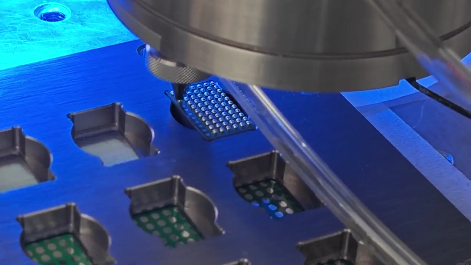
Laser solder ball jetting melts the ball at the nozzle and uses gas-assisted transfer toward the target, so a heated bar does not contact the joint area. The workpiece still needs support: the nozzle-to-target relationship depends on the fixture, datum, motion and—where useful—vision reference.
Hot bar soldering uses a heated tool that contacts the connection. Tool face, connection layout and FPC support must be considered together so that the intended contact is repeatable and nearby areas are not inadvertently contacted. In either method, the fixture establishes local flatness, the working datum, protection of selected areas and a practical loading relationship. The difference is not whether a fixture is needed, but what tool-to-workpiece geometry the fixture must make repeatable.
Match the joint form and heat path to the selected process
A localized solder-ball process may be evaluated when the solder volume, target position and nozzle approach can be defined for individual joints or a programmed sequence. The documented Dayan sequence combines ball delivery, local melting, gas-assisted transfer, programmable motion and application-specific workholding.
A hot-bar process may be evaluated when a heated contact tool matches the connection form and the FPC and mating features can be held beneath it. Neither description predicts material response or final suitability. Pad finish, materials, solder condition, joint geometry, fixture contact and nearby features all need validation on the intended FPC and mating component. Select the test arrangement around the actual connection rather than a generic preference for non-contact or contact heating.
Plan fixtures, reference and cycle time together
For laser jetting, confirm access to each target, nozzle clearance, local support and the reference that relates the FPC to the programmed path. Where vision is considered, the image feature, camera relationship, fixture and physical jetting point form one chain. The available ±10 μm vision-positioning reference belongs to one described system and is not a final joint-position claim for every FPC.
For hot bar soldering, review the tool-contact geometry and the arrangement holding the FPC and mating feature at the point of contact. A practical fixture must allow loading, support, reference and removal. The reference of up to 6 dots/s cannot be multiplied by joint count to claim a laser workpiece cycle. Both processes require a cycle boundary that includes placement, support, reference, processing, inspection and unloading.
Validate the sample, not a headline claim
Begin with close-up photos and drawings where available. Record pad and terminal information, FPC condition if known, mating component, access direction, current method, joint sequence and inspection criteria. Representative samples allow the fixture and process relationship to be evaluated on the actual assembly.
For laser jetting, record the candidate ball, support, datum, motion relationship, nozzle access and use of vision where relevant. The available reference describes approximately 0.2–0.9 mm solder-ball application for one configuration; the 0.25 mm ball on a 0.4 mm pitch test pattern is a demonstration, not a minimum-pitch or qualification claim. For hot bar, record the contact arrangement, FPC support, loading relationship and inspection method. Assess both conditions against the customer-defined acceptance criteria.
Use a decision checklist before choosing a route
Ask what exact FPC feature joins to which mating feature and what joint form is required. Map whether the target can be approached by a nozzle path, a contact tool or both. Identify local support, the datum, bend-area protection and nearby features. Define whether the connection should be evaluated as discrete target positions, a contact-tool interface or another arrangement.
Then agree which actions sit inside the cycle boundary and what evidence will be used to judge the sample. This checklist does not decide the process in advance. It creates the information needed to run a useful application review, compare representative conditions and select a fixture, equipment path and automation discussion that match the actual FPC connection.