
Start with the joint and manufacturing step
Define the connection before comparing equipment. Is the task a discrete local joint, a terminal connection, a lead or another form that needs a controlled material path? Record the pad or terminal shape, desired joint form, nearby components, approach direction, workpiece orientation, current method and inspection requirement. On FPC assemblies, local support, flatness and a bend area can determine whether either material-delivery approach can be presented consistently.
The selection question is not whether one process has a universally better result. It is whether a particular material-delivery method can be paired with the intended joint, fixture and manufacturing sequence. Start by mapping the workpiece position and the part of the flow in which soldering occurs. A clear map helps separate a process decision from a broad technology label.
Compare discrete solder balls with a wire feed path
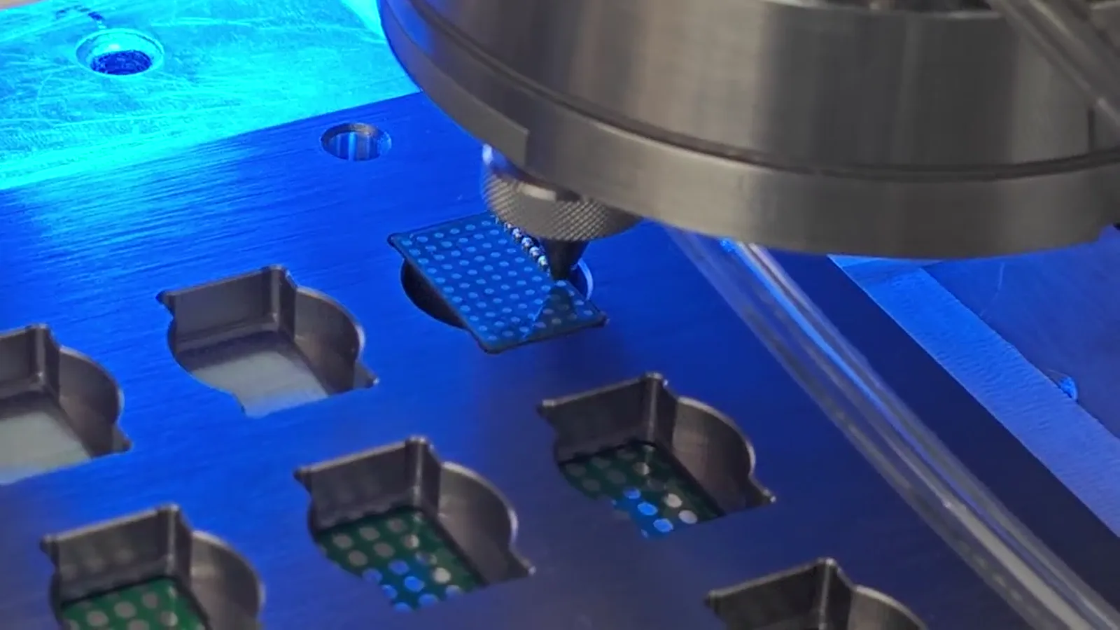
In laser solder ball jetting, an individual ball is fed and separated, melted at the nozzle and transferred toward the defined soldering position with gas assistance. The ball is a discrete input for the next processing event. In a laser wire process, wire is advanced through a feed path toward the heating and joint area. Both approaches still require a stable relationship between the tool, the workpiece and the intended connection.
The difference matters because the material path changes the access review. Ball jetting needs an appropriate nozzle approach and a clear transfer relationship to the target. Wire soldering needs a workable wire-end and heating approach. The fixture, part presentation and nearby clearance should be reviewed for the selected path rather than assumed to transfer unchanged from one method to another.
Match the solder input to the actual joint requirement
A solder ball provides a defined starting input for a local jetting event, while a wire feed presents solder along a different process path. In either case, selection should start with pad dimensions, lead or terminal shape, surface condition, clearance, target joint form and the inspection requirement. The documented ball-jetting information describes approximately 0.2–0.9 mm solder-ball application for one configuration. It is useful context, but it is not a universal range or a recommendation for every joint.
The process footage also demonstrates 0.25 mm solder ball processing on a 0.4 mm pitch test pattern. That demonstration should remain a test-pattern reference only. It does not select a ball for another part, establish a minimum pitch or determine the outcome of a different workpiece. A representative sample plan should identify the candidate material input, the joint to be reviewed and the criteria used to assess that condition.
Review access, part geometry and workholding as one arrangement
Access is more than an open line of sight. The process head needs an appropriate physical relationship to the joint while the fixture holds the component in a meaningful datum. For ball jetting, that relationship includes nozzle-to-workpiece clearance and the transfer path. For wire soldering, it includes the route that presents the wire end and heat at the connection without conflict with adjacent features.
Part geometry can change the comparison quickly. A narrow clearance may make one path easier to evaluate than the other, but a photograph alone does not establish the result. The fixture may need to provide local support, protect adjacent areas, maintain FPC flatness or present the joint in another orientation. Programmable motion only has value when the part reference is stable. Where an image-based reference is useful, vision is evaluated with the fixture and datum; a documented ±10 μm vision value belongs to one system and does not define final joint position for every application.
Evaluate automation and maintenance through the complete sequence
Either delivery method can be considered within a standalone, dual-station, inline or custom automation discussion after the local process is understood. The usable sequence includes loading, part presentation, fixture actions, reference establishment, motion, material delivery, soldering, inspection and unloading. For ball jetting, the available reference of up to 6 dots/s is a maximum point-processing frequency for one configuration, not a complete part cycle or a comparison with a wire cell.
Maintenance questions should follow the selected architecture. Ball jetting calls attention to the feed and separation path, guide channel, nozzle condition and their relationship to the fixture. A wire process calls attention to wire feed, wire presentation and access to the process point. The goal is not to declare one approach lower-maintenance. It is to make cleaning, material change, service access and the condition checks required by the application visible before the production concept is fixed.
Build a selection checklist before testing
A productive comparison identifies the evidence needed before a conclusion. Provide a close-up image or drawing of the exact connection; state whether the process question involves a discrete local joint, a wire presentation or both; map the available nozzle and wire paths; and describe the fixture, datum, part orientation and loading method. Add the current method, joint count or path, inspection requirement and the manufacturing flow you expect to evaluate.
Representative samples give the strongest basis for comparing the selected arrangements because they let the material path, access, support, reference and acceptance method be assessed together. Keep any conclusion bounded to the tested component and conditions. If the feed method, fixture, part presentation or acceptance requirement changes, treat the new arrangement as a new evaluation condition rather than a direct substitution.