
Start with the documented transfer sequence
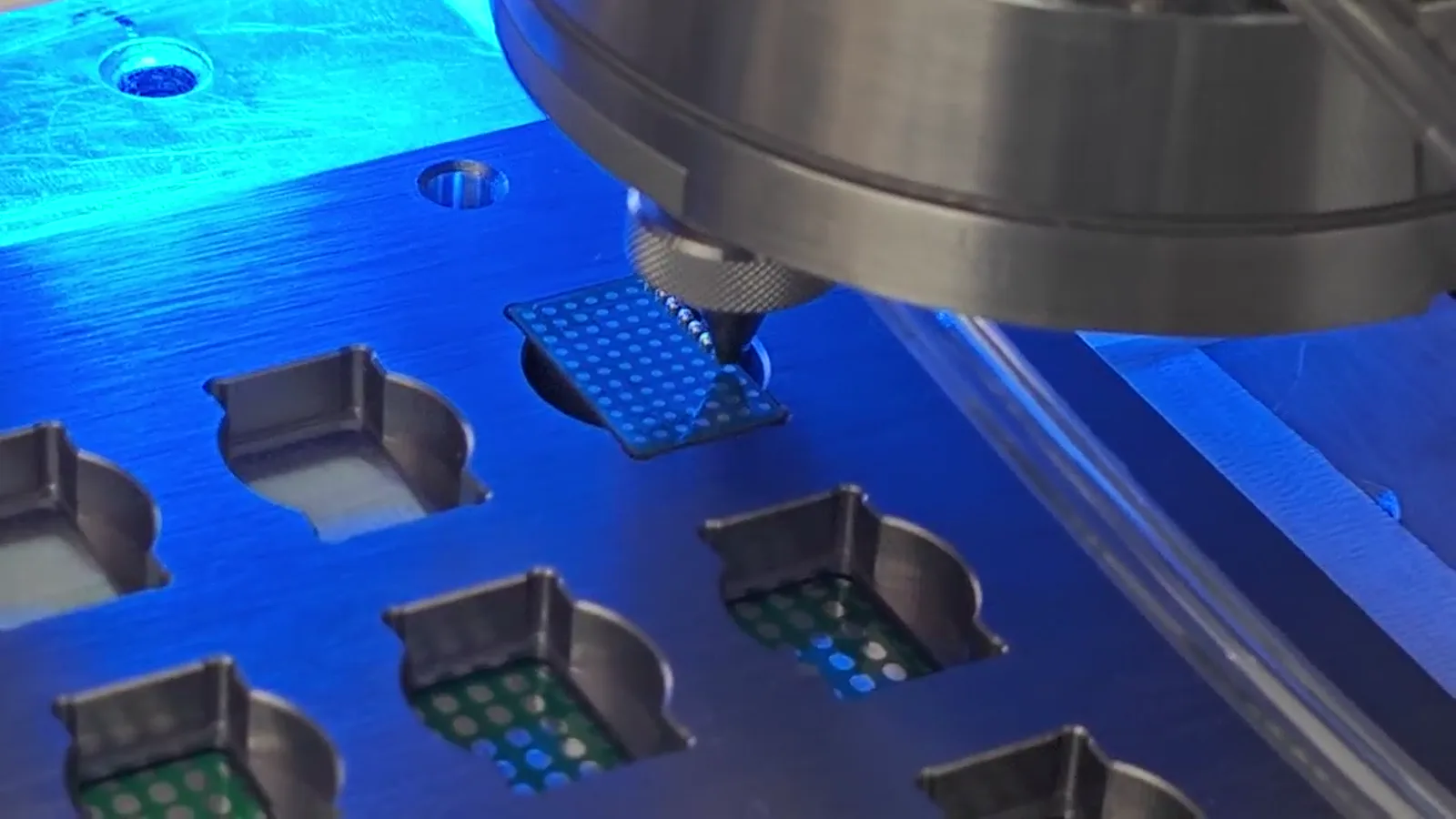
A precise discussion begins with what is actually shown and described. The process feeds a solder ball, separates an individual ball, melts it with laser energy at the nozzle, then uses gas-assisted transfer to move the molten solder toward a defined position on the workpiece. The nozzle and workpiece relationship is visible in supplied process material, along with fixture support and multiple workpiece positions. This is a sequence of coordinated actions, not an isolated gas step. The ball must arrive at the process head, the nozzle must be presented to the intended location, and the workpiece must be held in a usable reference before a meaningful sample can be assessed. Gas-assisted transfer belongs within that chain. It should not be described as a separate proof of joint quality, a substitute for workholding, or evidence that an unspecified gas will deliver a particular result. A project review can use the sequence to identify where a gas condition is relevant, but the review needs the actual part and a stated acceptance method before it can reach an application conclusion.
What the supplied information does and does not say about nitrogen
The supplied evidence uses the term gas-assisted transfer. It does not name nitrogen as the transfer gas, establish its purity or supply condition, state a pressure or flow value, or describe an effect on solder, pads, surrounding features or finished joints. It also does not compare nitrogen with another gas. For that reason, a reference to nitrogen in an enquiry should be treated as information to clarify, not as a property that can be inferred from a process video, machine photograph or general description. The enquiry can state whether nitrogen is required, already available, restricted, or simply under consideration. It can also state what the customer wants to observe during a sample evaluation. The resulting process discussion can then distinguish documented machine actions from customer-provided requirements. This boundary matters because a gas name alone does not define ball selection, laser condition, nozzle path, part support, position reference or acceptance. Those elements remain application-dependent even when a project supplies a preferred process-gas condition.
Treat gas as one item in a controlled process definition
For a practical evaluation, write the process definition as a set of connected decisions rather than a single question about nitrogen. The known process actions are individual-ball feed and separation, laser melting at the nozzle, and gas-assisted transfer toward the defined workpiece position. Around those actions sit the proposed gas condition, the ball selected for the sample, the location of the joint, the available nozzle approach, the fixture, the workpiece datum, motion path and any vision reference. The supplied documentation gives approximately 0.2–0.9 mm solder ball application for a documented configuration. That range is a configuration-specific reference, not a selection rule for every joint. A specific ball size should be evaluated against the real target rather than selected from the range alone. Likewise, a stated gas condition should be documented in the sample plan rather than assumed to determine the result. Keeping each item visible makes it easier to change one controlled condition during evaluation while preserving a clear record of what was tested.
Fixture, motion and datum establish the transfer target
Gas-assisted transfer moves molten solder toward a defined workpiece position, so the definition of that position is central. A fixture can support the workpiece and provide a mechanical datum. Motion relates the process head to that datum along the programmed path. Where the application calls for it, vision may be evaluated as part of the positioning strategy. These elements must be considered together: a camera reference does not remove the need for a stable presentation of the part, and a fixture by itself does not answer every image-reference or nozzle-access question. The supplied documentation cites ±10 μm vision positioning for one described system. That figure remains tied to its described system and conditions; it is not a general accuracy claim for another fixture, part surface, motion path or gas condition. During sample preparation, the team should identify the intended datum, the fixture contact and support areas, the expected head approach, and whether vision is to be assessed. This creates a complete location reference for the transfer step instead of reducing it to a gas label.
Read available numeric references within their configuration
Several supplied values provide useful context when they stay within scope. The documentation shows approximately 0.2–0.9 mm solder ball application, up to 6 dots/s, ±10 μm vision positioning for one described system, and 100/200 W laser configuration. None of these values defines a complete production process. The documented dot frequency is not total cycle time because the full sequence can include workpiece presentation, fixture actions, motion travel, any vision step, the individual soldering positions, inspection and handling. The laser configuration is not a statement that one power setting is appropriate for every workpiece. The vision figure is not independent of datum, fixture, calibration, image feature and physical relationship to the jetting point. Similarly, the ball-application range does not establish compatibility with an unspecified joint. A gas condition should be read with the same discipline: it is a configuration item to record and evaluate, not an independent specification that turns these other numbers into a universal promise.
Use the fine-pitch frame only for its stated demonstration
One supplied frame demonstrates 0.25 mm solder ball processing on a 0.4 mm pitch test pattern. It is useful visual evidence of that specific demonstration and no more. It does not define a minimum supported ball diameter, minimum pitch, customer product geometry, accuracy on another workpiece or production qualification. It also does not establish a particular nitrogen or process-gas condition. When reviewing a compact joint pattern, use the footage to understand the visible head, nozzle and test-pattern context, then return to the customer part. The actual fixture, datum, workpiece presentation, target locations and customer-defined acceptance criteria still require evaluation. The same restraint applies to supplied sample images and process or CCD footage. They can help frame the engineering conversation and show that process and positioning material exists, but they are not approved customer cases or a substitute for sample validation. A careful article should preserve the distinction between a demonstrated frame and a conclusion about a different assembly.
Build a sample evaluation around stated acceptance criteria
The most useful next step is a sample plan that names what will be assessed and how the result will be judged. Provide photographs and drawings where available, identify the intended soldering positions, describe the available nozzle access, and show how the workpiece can be supported or referenced. State the current process if there is one, the number and sequence of locations to be considered, and the customer-defined acceptance criteria. If nitrogen or another process-gas condition is a requirement, include that requirement explicitly rather than assuming it from the equipment description. The evaluation can then review the individual-ball delivery sequence, laser melting at the nozzle, gas-assisted transfer, fixture arrangement, motion, datum and optional vision as one controlled process concept. Observations should remain specific to the samples and conditions used. Any decision about final machine configuration follows application and sample evaluation, not a universal interpretation of a video, a numeric reference or an unverified gas-related expectation.