
Start by defining what the evidence does and does not say
The phrase flux-free can be useful for naming a process question, but it should not be used to skip the engineering definition of that question. The supplied documentation establishes a particular solder-ball jetting sequence and provides process and CCD video plus sample images. It does not provide approved customer cases, company photographs, brochures, competitor comparisons or universal production-qualification data. Nor does it establish material compatibility, metallurgy, gas effects, reliability, yield, universal thermal behavior or a result for a different assembly. That boundary is practical rather than restrictive. It prevents a generic label from being mistaken for a recommendation for every pad, terminal, surface condition or component layout. For a proposed part, the application owner can define the intended process scope, the condition to be examined and the evidence that will be accepted. The engineering team can then evaluate the documented process on representative samples instead of relying on an unrelated image or demonstration. A sound conclusion should identify the tested workpiece, fixture, position-reference method, selected conditions and customer-defined acceptance criteria. It should not extend beyond them.
Follow the documented solder-ball sequence
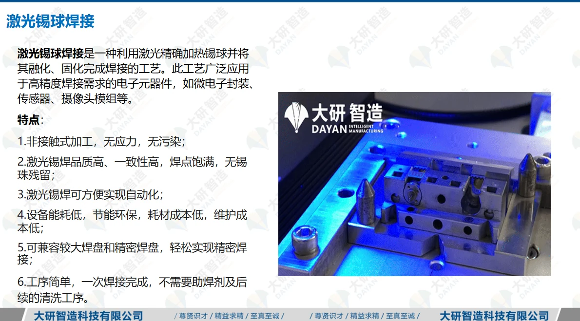
The documented process begins with solder-ball feeding and individual-ball separation. One ball is presented through the guide path for the cycle, rather than treating solder delivery as an unspecified background step. Laser energy melts that ball at the nozzle. Gas-assisted transfer then moves the molten solder toward the defined workpiece position. These actions form a connected sequence: delivery establishes the starting solder piece, the nozzle is the location of laser melting, and gas assistance is part of the transfer step. The workpiece relationship must already be meaningful when transfer occurs. The process should therefore be discussed as more than a laser setting or a ball size. Feed path, nozzle condition, position, fixture support and the programmed sequence all belong to the same evaluation. A process video can show this physical sequence and the relationship between the head and a workpiece. It cannot by itself show that another assembly, terminal layout or production flow will respond in the same way. A sample review should record what was actually processed and what was observed under the agreed evaluation conditions.
Treat fixture, motion and datum as one positioning strategy
The defined workpiece position is established by more than the motion system. A fixture supports and presents the part. A datum identifies the feature or reference from which the programmed location is meaningful. Motion relates the process head to that reference. Where an application needs it, vision can be assessed as another part of the reference strategy. This is why fixture, motion, datum and optionally vision should be evaluated together rather than selected as separate feature lists. A camera view cannot remove a poorly defined datum, and a stable datum cannot resolve access or support issues that the fixture has not addressed. The review should ask what feature represents the soldering position, how the workpiece sits in the fixture, whether the selected feature is visible when vision is considered, and how its location relates to the jetting point. Camera, lighting, field of view, calibration and the physical relationship between camera and nozzle remain application-dependent. The supplied documentation cites ±10 μm vision positioning for one described system. It is a configuration-specific reference, not a universal positioning statement for every workpiece, fixture or vision arrangement.
Read supplied configuration values in their proper scope
Technical values are most useful when their limits travel with them. The supplied documentation shows approximately 0.2–0.9 mm solder-ball application for a documented configuration. It shows up to 6 dots/s for a described system. It cites ±10 μm vision positioning for one described system and identifies 100/200 W laser configuration. Each item is configuration dependent. None should be treated as a machine-independent range, a universal accuracy, a total cycle-time commitment or a prescription for a new application. For example, a dot-frequency reference describes a stated process-rate condition, while a complete application sequence may also need positioning, fixture actions, vision, handling, inspection and other project-defined steps. Likewise, a laser configuration reference does not select a process condition for a different part. During evaluation, place the documentation value beside the relevant sample, joint location, workholding arrangement and acceptance criteria. That preserves its engineering meaning. It also makes it possible to distinguish between a useful configuration reference and a claim that has not been demonstrated on the proposed workpiece.
Keep the 0.25 mm ball and 0.4 mm pitch frame factual
One supplied frame demonstrates 0.25 mm solder-ball processing on a 0.4 mm pitch test pattern. That is a specific process visual, and it should retain exactly that scope. It does not define a minimum pitch, a minimum feature size, a universal ball recommendation or a production condition for every component with similar nominal spacing. Pitch alone does not describe the whole workpiece relationship: the target location, nearby features, available approach, part presentation, fixture support and position reference still need review. The demonstration is useful because it provides a real example of the documented sequence at a stated test pattern. It is not a substitute for examining the proposed joint. A careful engineering discussion can use the frame to explain why the ball, nozzle and target must be related to a specific geometry without assigning unverified dimensions, accuracy, yield or reliability to a different design. If a prospective part appears comparable in one respect, that observation should simply guide the questions for sample validation; it should not become a capability conclusion.
Build a sample-validation plan around observable questions
A useful evaluation begins with information that makes the workpiece and intended judgment clear. Photographs and drawings where available can identify the target location and surrounding geometry. The process review can document the fixture concept, chosen datum, motion path, whether a vision reference is to be evaluated, and how the individual ball will be presented and transferred toward the workpiece. The application owner should define the acceptance criteria rather than assume an inspection threshold from supplied images. The sample-validation record can then state what condition was tested, which process elements were considered and what evidence was reviewed. This approach distinguishes a controlled process evaluation from a broad production claim. Supplied sample images and videos are suitable as real process context; they are not approved customer cases and do not establish a quality result for an unrelated design. If an observation is made on the sample, it should be tied to the tested configuration and the stated criteria. If a question remains open, it belongs in the next evaluation step rather than in an implied promise.
Use the findings to define, not assume, the next configuration
After sample validation, the findings can guide an application-specific equipment discussion. The objective is not to force the workpiece into a generic specification. It is to identify whether the ball-delivery sequence, nozzle access, fixture, motion, datum and optional vision arrangement form a coherent process for the evaluated condition. Configuration choices should follow the evidence produced during that work. A documented 100/200 W laser configuration, an approximate ball-application reference, a dot-frequency reference or a vision-positioning reference may be relevant to that discussion, but each remains tied to its supplied or tested context. The evaluation record should also separate what has been observed from what requires further work. This protects against turning a process visual into a universal production, reliability or qualification claim. For flux-free laser soldering, the most useful engineering message is therefore disciplined scope: define the proposed process, test representative samples, review against customer-defined acceptance criteria and document the resulting configuration decision only as far as the evidence supports it.