
Define the cycle boundary before calculating anything
Cycle time has no useful meaning until the team agrees what starts and ends the measured sequence. For one evaluation, the boundary may be the first defined process-ready position through the final processed position. For another, the customer may need the boundary to include part presentation, position confirmation or a result review. The correct boundary is the one that matches the intended operating sequence and the customer-defined acceptance criteria. State it in plain language before discussing seconds, rates or equipment configuration. This avoids comparing a localized soldering event with a broader workpiece sequence as though they were the same measure. It also makes clear which elements are demonstrated, which are assumed and which still need sample validation. A cycle-time estimate is most useful when its start, finish and included actions are explicit rather than implied by a machine value.
Read a dot-rate value as one part of the sequence
The supplied documentation shows a maximum soldering frequency of up to 6 dots/s for a described configuration. This is a documented maximum frequency, not a complete process commitment. It describes a rate associated with dots in that configuration; it does not by itself define how quickly a particular workpiece passes through an application-specific sequence. A real part may have one defined position or several positions, and the process must relate the head to each intended location. The evaluation therefore keeps the dot-rate reference separate from the cycle boundary, number of defined positions, motion path and position-reference approach. Do not multiply a joint count by the published maximum and call the result a guaranteed cycle time. Instead, record the value as configuration-scoped information and use the real sequence to determine what requires further observation.
Map the soldering event at each defined position
At every intended workpiece position, the documented process involves individual-ball feed and separation, laser melting of the ball at the nozzle, and gas-assisted transfer of molten solder toward the target. The timing discussion should identify whether this documented event is repeated unchanged at each position or whether the defined sequence calls for a different reference, path or condition. The purpose is not to assign unsupported durations to individual actions. It is to make the planned order visible so that the evaluated process can be compared with the customer requirement. An estimate that names only the laser action omits the relationship between ball delivery, nozzle, workpiece and next position. A useful review also records the selected configuration rather than assuming that one observed rate applies to every ball application or process setup. The supplied approximately 0.2–0.9 mm ball-application range is documented for a configuration and remains application dependent.
Evaluate fixture, datum, motion and vision as one reference chain
A workpiece position is not defined by motion alone. The fixture supports how the part is presented, the datum establishes the reference, and motion relates the nozzle to that reference. Vision may be evaluated when the application calls for an image-based reference, but it must be considered with the fixture and datum rather than treated as an isolated feature. For cycle-time evaluation, describe the reference sequence that the intended process actually requires. If a fixed fixture datum is used, identify that choice. If a vision step is proposed, identify the feature and how it relates to the jetting position. The supplied documentation cites ±10 μm vision positioning for one described system; it is configuration dependent and not a general positioning statement for every part. The value should not be used to infer a cycle duration, a universal accuracy or a result on an untested assembly.
Treat movement between positions as part of the application question
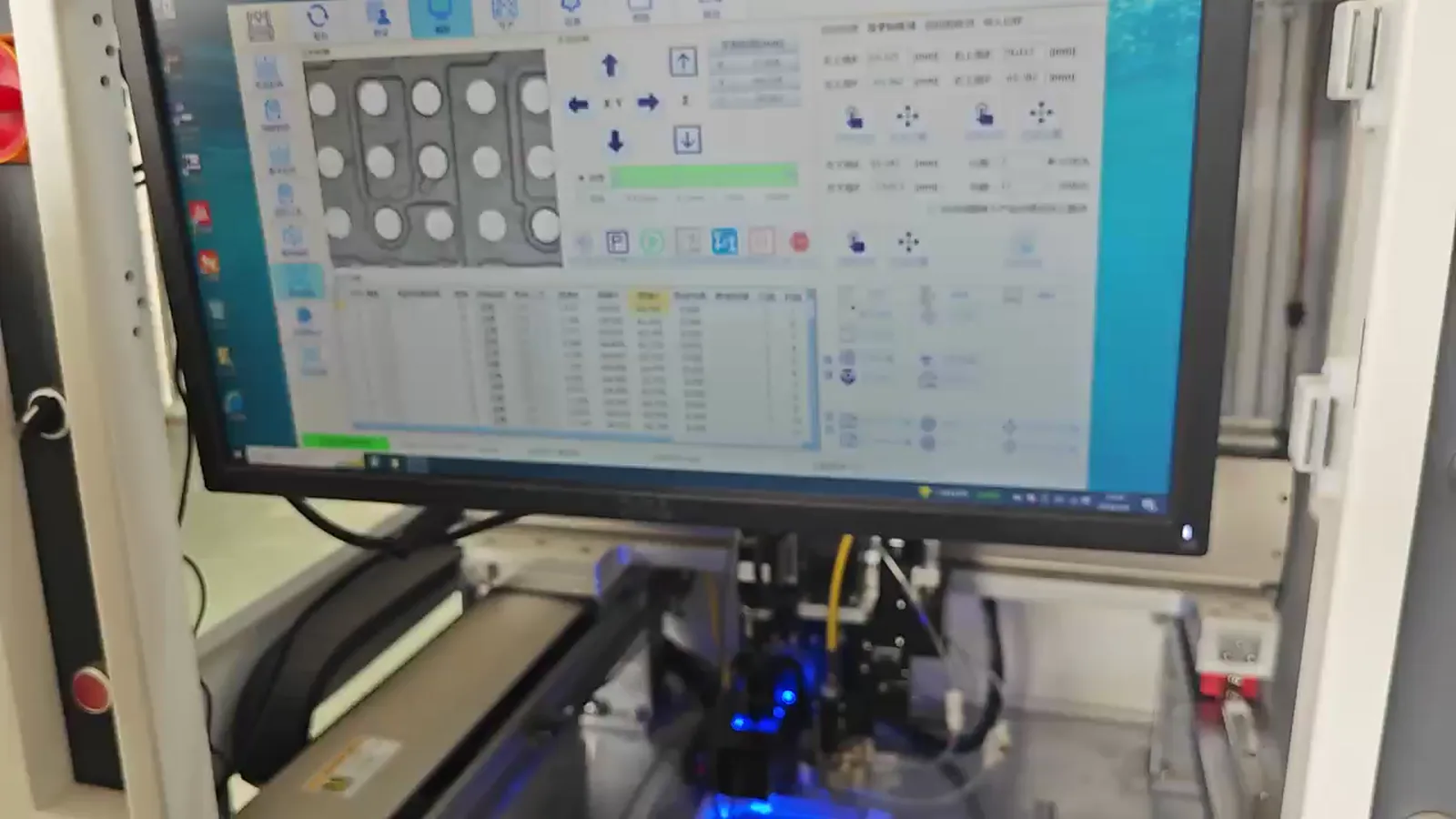
When a workpiece has more than one defined soldering position, the order of positions and the motion relationship between them belong in the cycle-time review. A programmed sequence may need to establish the intended workpiece relationship, complete a localized soldering event and move to the next position. The meaningful question is not whether motion exists, but what path and reference strategy the actual fixture and workpiece require. A short-looking arrangement in an image does not supply the information needed for another part. Similarly, the supplied CCD machine-operation frame provides process and positioning context; it is not a timed production record. Keep the proposed position order, datum method and any use of vision visible in the evaluation record. That makes it possible to discuss the sequence without representing a supplied video, frame or sample image as universal production evidence.
Use a structured estimate instead of a headline calculation
A responsible estimate separates the documented inputs from the application inputs. The documented inputs available here are the individual-ball process sequence, the configuration-dependent references of approximately 0.2–0.9 mm ball application, up to 6 dots/s, ±10 μm vision positioning for one described system, and 100/200 W laser configuration. Application inputs must be supplied or evaluated for the intended workpiece: the defined positions, fixture and datum arrangement, motion sequence, whether vision is used, and the customer-defined acceptance criteria. None of those inputs should be filled with a value copied from an unrelated example. The table provides a simple record format. It is designed to expose missing information before a cycle-time figure is presented, not to manufacture a value from incomplete data.
Validate the proposed sequence with representative samples
Sample validation connects the written sequence to the actual workpiece. It gives the team an opportunity to evaluate the feed, separation, nozzle-to-position relationship, fixture, datum, motion and optional vision approach together. The observation should remain limited to the tested sample, selected configuration and agreed acceptance criteria. It should not be expanded into claims about material compatibility, reliability, yield, production qualification or another customer product. The supplied fine-pitch frame is likewise narrow evidence: it demonstrates 0.25 mm solder ball processing on a 0.4 mm pitch test pattern only. It does not establish an unspecified minimum pitch or a total-cycle-time capability. After an application-specific sample review, the cycle-time record can distinguish observed sequence elements from items that still require engineering evaluation.