
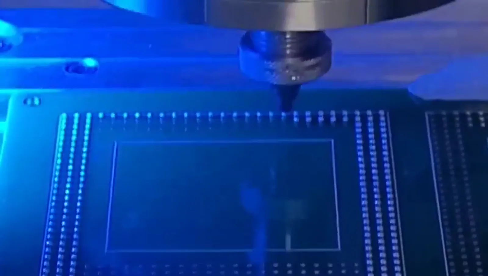
Define the measure before discussing the factors
The phrase cycle time can refer to different boundaries unless the boundary is stated. A discussion of a localized soldering event is narrower than a discussion of an entire workpiece sequence. The documented solder-ball event has a clear order: a ball is fed and separated, laser energy melts it at the nozzle, and gas-assisted transfer moves the molten solder toward a defined position. That order supplies a factual basis for describing the event, but it does not supply a universal elapsed time for a workpiece. The position itself also has to be defined through the fixture, datum and motion relationship, with vision included when the chosen setup uses it. Before a rate is cited, the technical record should say whether it concerns the documented dot event or a wider sequence involving the workpiece reference and its defined positions. This distinction prevents a configuration value from being used as if it were a measured total for every arrangement. It also makes the question answerable: which portions of the sequence are documented, which are specific to the intended setup, and what boundary would a cycle-time statement actually represent?
Keep the solder-ball event intact
The individual solder ball is not merely a quantity attached to the end of a sequence. It is the starting input to a documented series of actions. Individual balls are fed and separated before laser energy melts the ball at the nozzle. Gas assistance then transfers the molten solder toward the defined position. A cycle-time discussion that names only laser melting leaves out the documented feed, separation and transfer elements. Conversely, a discussion that names ball feed but does not describe the nozzle and target relationship is incomplete. The useful unit is the whole documented event, expressed in its actual order. This does not justify assigning unsupported durations to the individual actions or treating any one of them as the only rate-setting item. It does provide a disciplined way to identify what a dot-rate figure does and does not cover. For an intended setup, the record can preserve the event as feed and separation, melting at the nozzle, and gas-assisted transfer, rather than replacing that sequence with a generic claim about fast soldering.
Position reference is part of the sequence
A defined soldering position exists only in relation to a workpiece reference. Fixture support, the selected datum and programmed motion work together to establish that relationship. Where vision is part of the application, it should be described as part of the same chain rather than as a separate promise. The supplied documentation cites ±10 μm vision positioning for one described system. That figure is tied to that system and its configuration; it is not a positioning statement for every fixture, datum, part presentation or vision use. In cycle-time terms, the important question is not whether a camera is present, but what position-reference approach the specific process calls for. A fixed datum, motion path and optional vision routine should be named in the sequence definition before a complete time is asserted. This keeps the nozzle-to-workpiece relationship visible in the review. It also avoids an invalid shortcut in which a vision-positioning value is converted into a timing result, or in which motion is treated as though it establishes the target independently of the fixture and datum.
Motion relates the nozzle to each defined position
Motion is the link between the programmed process and the defined workpiece position. Its role has to be read with the fixture and datum, because the motion command is meaningful only when the workpiece has an established reference. Where an array-oriented sequence is considered, the defined positions and their programmed relationship should be recorded rather than inferred from a single frame. The supplied array-oriented media provides visual process context; it does not provide a timed record for another workpiece. The same restraint applies to any position order: it is an application-specific part of the sequence, not a property established by a laser-power or dot-rate reference. For cycle-time review, identify the intended defined positions, the fixture and datum that support them, and the motion approach that relates the nozzle to them. If vision is used, identify it with that same reference chain. This method does not manufacture a number. It makes visible the process information that must be resolved before a number can mean more than a headline.
Read configuration values within their stated scope
The supplied documentation states a maximum soldering frequency of up to 6 dots/s for a described configuration. It is a configuration-dependent frequency reference, not a universal total cycle time. It cannot be converted directly into a complete workpiece result without first defining what is included in the cycle and how the intended positions are referenced. The documentation also identifies 100/200 W laser configuration. That is likewise a configuration reference, not a reason to assume a single process condition or a timing value for a new setup. Approximate 0.2–0.9 mm ball application belongs to the same category: it is documented for a configuration and should not be recast as a universal selection or rate claim. These values can be retained in an engineering record as scoped facts. What they cannot do is replace the missing description of fixture, datum, motion, optional vision and defined workpiece positions. Keeping each value beside its scope is more technically useful than combining them into a specification the source does not state.
Use the fine-pitch footage only as demonstration context
The supplied footage includes a test-pattern demonstration marked 0.25 mm ball and 0.4 mm pitch. Its factual meaning is specific: it demonstrates 0.25 mm solder ball processing on a 0.4 mm pitch test pattern. It does not define a minimum pitch, a universal ball-size capability or a cycle-time result. In particular, the frame should not be used to infer a rate for a different array, fixture, datum strategy or motion path. It may be used to illustrate that the process documentation includes array-oriented localized soldering context, but the article should retain the distinction between a visible demonstration and a timing statement. The same distinction applies to the supplied media selected for this page. A process frame can show a sequence context; it cannot establish the duration, configuration or position-reference conditions of an unshown application. When discussing cycle time, retain the demonstrated 0.25 mm ball / 0.4 mm pitch facts exactly and leave all other pitch and timing conclusions to the defined setup.
Build a cycle-time record from named process factors
A concise technical record can keep the conversation evidence-based without inventing a complete time. First, state the intended cycle boundary in plain language. Next, list the documented solder-ball event: individual-ball feed and separation, laser melting at the nozzle, and gas-assisted transfer toward the defined position. Then identify the workpiece-reference chain: fixture, datum, motion and whether vision is used. Record the defined positions and the selected configuration information separately, including any use of the documented approximate 0.2–0.9 mm ball-application reference, up to 6 dots/s frequency reference, ±10 μm vision-positioning reference for the described system, or 100/200 W laser configuration. Each item should remain attached to its own stated scope. Finally, mark which inputs have been defined for the intended setup and which have not. This approach is intentionally different from calculating a number from an unrelated frame or a single maximum value. It creates a clear handoff between documented process facts and the information required for an application-specific review, while preserving the limits of the supplied evidence.