
Start with the component-specific question
The term heat-sensitive describes an engineering concern, not a completed process conclusion. Before selecting a machine format or quoting a performance value, define the workpiece location to be soldered, the surrounding features that must be considered, the available approach to that location and the condition in which the workpiece will be presented. The review should also identify what the application owner wants to inspect and what customer-defined acceptance criteria will be used. This keeps the discussion tied to the actual component rather than to a category label. For this type of application, the practical question is whether the documented process sequence can be configured and evaluated around the intended workpiece. A supplied process video or sample image can illustrate a process relationship, but it is not a customer case, a compatibility statement or a production result for another part. The appropriate conclusion follows sample validation on representative workpieces, with the conditions and acceptance criteria recorded for that evaluation.
Use the documented sequence as the process baseline
The available process facts describe a defined sequence. An individual solder ball is fed and separated. Laser energy melts that ball at the nozzle. Gas-assisted transfer then moves the molten solder toward a defined position on the workpiece. The sequence provides a practical basis for discussing a localized soldering event, but it should not be reduced to a laser-setting discussion. The ball, nozzle, workpiece position and transfer action belong to the same process event. For heat-sensitive-component work, each event should be examined in the order it occurs. First, establish how the workpiece is held and referenced. Then confirm whether the nozzle can approach the intended position in the proposed presentation. Next, evaluate the selected process condition on samples and review the result against the agreed criteria. Treating these as connected decisions is more useful than inferring suitability from a video frame, a single setting or a product label. The supplied materials support a process-evaluation approach, not a universal operating recipe.
Fixture, motion and datum define the real target relationship
A defined workpiece position is created by more than a coordinate in a program. The fixture, workpiece support, motion system and datum strategy establish the relationship between the nozzle and the intended soldering location. For a heat-sensitive component, this relationship should be considered together with the arrangement of the part during loading, processing and review. A fixture is therefore not a separate accessory decision: it is part of the evidence needed to evaluate the process on the intended workpiece. A mechanical datum may be sufficient for one application. In another, a vision reference may be considered when the component presents a usable feature and the proposed setup calls for it. If vision is used, the image reference, motion relationship and physical jetting position should be evaluated as one chain. The supplied documentation cites ±10 μm vision positioning for one described system. That value belongs to its documented configuration and does not establish positioning accuracy for every fixture, datum, vision condition or component.
Frame evaluation around access and part presentation
Heat-sensitive-component evaluation benefits from a clear, repeatable description of how the part arrives at the process position. Record the orientation, the local area to be soldered, the available nozzle approach, the features used for the datum and the fixture contact points. These details make it possible to discuss what the supplied jetting sequence is being asked to do on the real assembly. They also prevent assumptions based on unrelated process footage. The fixture, motion path and any vision routine should be assessed as a combined arrangement. A vision result cannot stand in for stable workholding, and a stable fixture does not automatically remove the need to verify the workpiece position. The customer-defined acceptance criteria should be identified before sample review, so that images and observations are evaluated against a known requirement. This approach does not assume a thermal outcome or material compatibility. It simply creates a disciplined way to test whether the proposed process arrangement is appropriate for the specific component.
Read solder-ball evidence within its documented scope
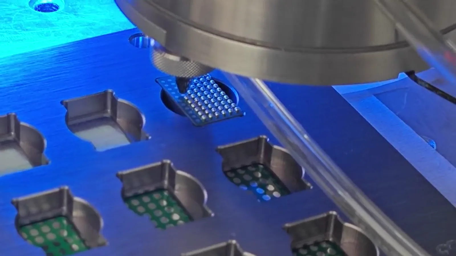
Solder-ball selection is an application decision that belongs with the intended workpiece position and customer-defined acceptance criteria. The supplied documentation shows approximately 0.2–0.9 mm ball application for a documented configuration. This is useful context for an engineering discussion, but it is not a universal range, a recommended size for a particular component or a statement that every joint can be addressed within those values. The selected condition should be evaluated on representative samples. The supplied frame marked 0.25 mm solder ball and 0.4 mm pitch has a similarly narrow factual meaning. It demonstrates 0.25 mm solder ball processing on a 0.4 mm pitch test pattern only. It does not define a general pitch limit, a minimum ball size, an accuracy claim or a result on another workpiece. In a heat-sensitive-component review, the most responsible use of this evidence is to distinguish documented demonstration context from the sample validation still needed for the proposed assembly.
Keep configuration figures separate from application conclusions
The supplied system information includes a 100/200 W laser configuration, up to 6 dots/s, and ±10 μm vision positioning for one described system. Each figure is configuration dependent. The laser reference identifies a configuration option; it does not prescribe the setting or configuration for a heat-sensitive component. The vision value remains tied to its documented system and conditions. The dot-rate reference is a stated maximum for a described configuration, not a complete process-time or production-throughput conclusion. For a practical review, these figures may be listed as background information alongside their limits of interpretation. They should not be combined into a generic capability claim. The complete workpiece sequence may include fixture loading, datum establishment, optional vision, programmed motion, soldering, inspection and unloading. The supplied facts do not establish how those elements will apply to a new part. Final configuration should therefore follow application review and sample validation rather than be inferred from individual published values.
Build sample validation into the engineering decision
A sample-led review converts a broad concern about heat sensitivity into an application record. Begin with representative workpieces, close-up images or drawings where available, the proposed soldering location, the preferred part orientation and the acceptance criteria that the customer defines. Use this information to prepare the fixture and datum concept, decide whether a vision reference is worth evaluating, and set out the programmed process sequence. The goal is not to claim a universal result; it is to make the assumptions and observed sample conditions visible. During review, distinguish the supplied process evidence from the new application evidence. The site’s videos and images show real supplied process, CCD and sample context, but they are not approved customer cases or qualification data. A process frame can support a discussion of nozzle-to-workpiece relationship. A sample image can support a visible review of the tested item. Neither should be used to imply customer ownership, production acceptance, reliability or performance on an untested component. After sample validation, the process proposal can state the tested arrangement, open items and customer-defined acceptance criteria without extending the conclusion beyond the evaluated application.