
Begin with a meaningful datum
The first vision question is not which camera to buy. It is what feature should define the soldering location. Depending on the part, that reference might be a fiducial, an edge, a terminal, a pad pattern or a fixture feature. The selected datum should be visible under the planned lighting, stable on the real workpiece and relevant to the joint being processed. If the component can move in the fixture, or if the chosen feature does not represent the joint accurately, an image alone cannot make the process repeatable. A sound review therefore considers the component datum, fixture support and soldering path together.
What the camera contributes
A vision system can help locate a part feature, check a reference position or support a programmed correction before the soldering sequence. Its contribution is defined by the image it can reliably produce, not by a generic camera label. Surface finish, contrast, reflections, contamination, feature size, lighting direction and field of view all affect whether the intended reference can be identified. The image strategy should be tested with representative components and the actual fixture, because a clear photograph or demonstration view does not establish that every production surface will be equally easy to locate.
Camera-to-jetting calibration
The camera observes one location while the solder ball is delivered from another physical location. Calibration establishes the transformation between those coordinate systems: the image reference must be related to the motion axes and then to the nozzle or jetting point. This relationship can be influenced by camera mounting, working distance, lens selection, motion geometry, fixture position and any change in the process head. Calibration should therefore be treated as an engineering task with a defined procedure and verification sample. A vision result is only useful when the corrected position reaches the intended joint under the conditions of the application.
Vision and fixture strategy are connected
Vision positioning does not remove the need for a repeatable fixture. Workholding controls how the part is presented, protects sensitive features and establishes the starting relationship for the motion sequence. A mechanically defined datum may be sufficient for some parts; another application may benefit from an image reference because component placement or a feature varies within the process. In either case, the design review should identify which variation is being corrected and which variation must be controlled by the fixture. The aim is not to add vision by default, but to use it where it addresses a specific positioning problem.
From image result to soldering sequence
Once a reference is located, the result must be passed into the programmed motion path in a controlled way. The sequence may include part detection, image capture, feature recognition, coordinate correction, movement to the joint, individual solder-ball delivery and inspection or the next programmed point. Multiple joints require attention to how one reference is applied across the path and whether the part remains stable during processing. Access around nearby components, nozzle approach, work distance and the order of points can be as important as the initial image. Process development should document the reference used, the correction logic and what is checked after the soldering operation.
Evidence-led evaluation
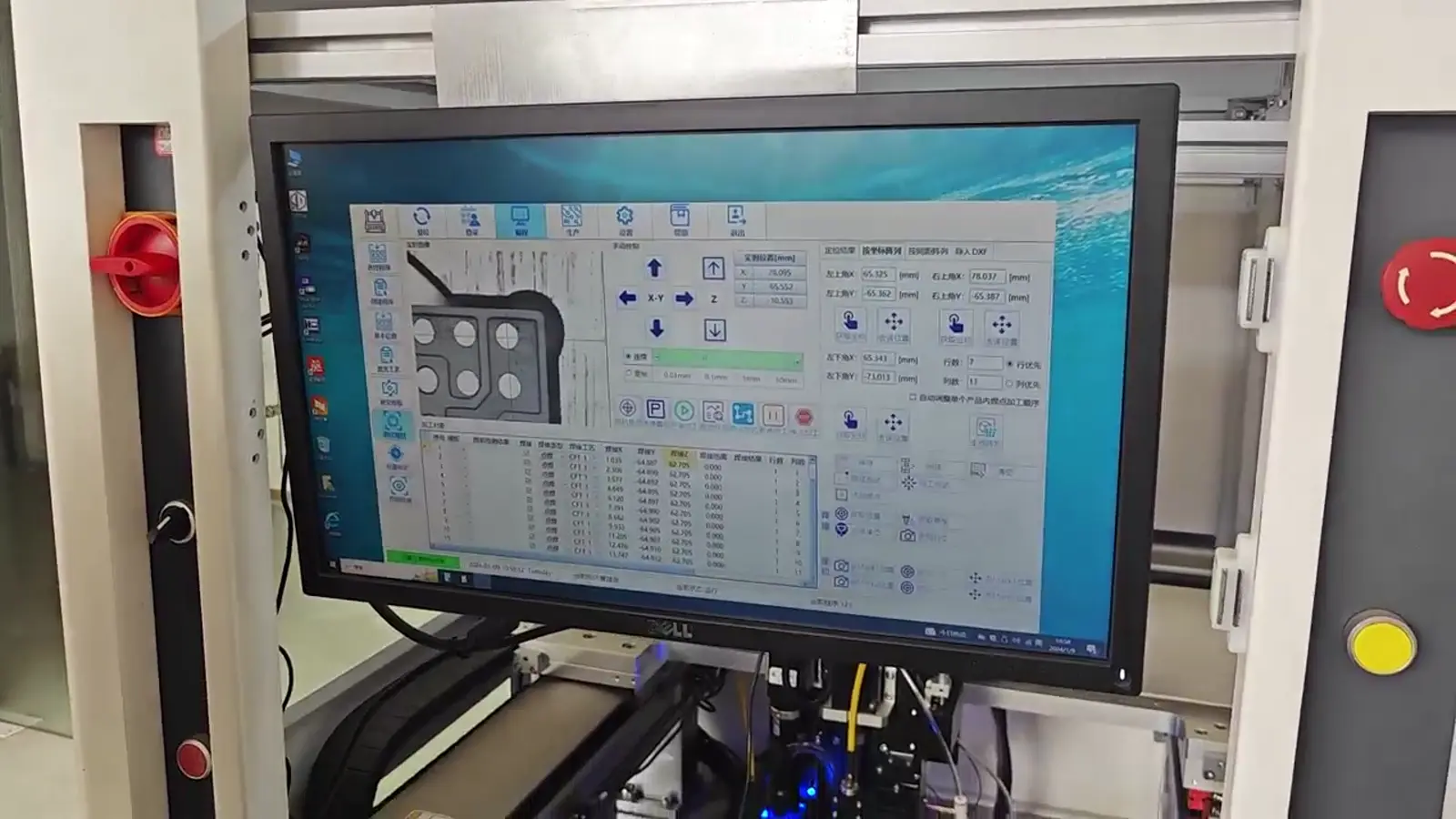
The supplied CCD and machine-operation footage is useful for showing vision-positioning and software context, while the real jetting footage shows the broader relationship between process head, workpiece and soldering sequence. These materials explain the process concept; they do not by themselves qualify a new component. A practical evaluation uses photographs, drawings where available, joint and pad information, fixture constraints and representative samples. The review can then determine whether a mechanical datum, vision reference or combined strategy is appropriate, and whether the selected image conditions remain stable on the actual part.