
Compare methods against one defined joint
A small electronic joint is not a sufficient comparison unit by itself. Before considering laser soldering or a hand-soldering approach, identify the exact workpiece position that is to be evaluated and how that position will be recognized. Describe the component presentation, the available access around the target, the proposed datum and the result that the customer intends to judge. This gives both methods a common basis. Without it, a comparison can drift into a list of generic advantages that says little about the actual part. For the documented laser process, the target is a defined workpiece position reached through a coordinated relationship among fixture, datum and motion. A hand-soldering proposal should be recorded with equally clear information about the intended joint and the planned evaluation conditions, rather than being treated as an unspecified baseline. The goal is not to declare a winner from a method name. It is to make a decision that remains traceable to the joint, the part presentation and the agreed review criteria. If the target or the part reference is unclear, resolving that issue is more informative than assigning a method based on a headline specification.
Use the documented laser sequence as a process map
Laser solder-ball jetting is best understood as a sequence, not as a single energy event. An individual solder ball is first fed and separated. Laser energy melts that ball at the nozzle. Gas-assisted transfer then moves the molten solder toward the defined workpiece position. Fixture support, datum and motion establish the relationship between that transfer and the workpiece; optional vision can be part of the same positioning arrangement. This sequence gives a structured checklist for a comparison. Ask how the solder input is defined, where melting occurs, how the molten solder is moved toward the target, and how the part is located relative to the nozzle. Then ask what corresponding process description is available for the hand-soldering option. The answer need not assume that either approach is suitable or unsuitable. It should show whether each option has enough application-specific information for a sample evaluation. Treating the laser process as this complete chain also prevents an isolated laser setting, a nozzle image or a visible sample from being used as a substitute for workholding and position-reference planning.
Make workholding and datum part of the comparison
A programmed position has meaning only when it is connected to a physical reference. In the documented laser arrangement, the fixture supports the workpiece, the datum establishes a reference and motion follows the selected sequence toward the intended position. These elements should be considered together. A fixture does not independently establish the final relationship to the nozzle, and a motion coordinate does not by itself explain how the component has been presented. Where vision is evaluated, it is another part of this reference chain rather than a detached accuracy claim. The supplied information cites ±10 μm vision positioning for one described system. That number must remain tied to that system, its configuration, its image conditions, its datum strategy and its fixture arrangement. It is not an accuracy promise for every part or a basis for claiming a result from another setup. For a fair comparison, document the laser fixture and reference strategy alongside the proposed hand-soldering workholding and reference approach. If either option changes its fixture, datum or part presentation, that change should be visible in the sample plan and in the interpretation of the result.
Separate configuration references from application conclusions
Technical values are useful only when their scope stays intact. The supplied documentation describes approximately 0.2–0.9 mm solder ball application for a configuration. It also identifies 100/200 W laser configuration and up to 6 dots/s for a described configuration. These references identify aspects of the documented system; they do not combine into a universal specification, select a setup for a new workpiece or establish complete production timing. In particular, dots per second is not the same as a full process cycle. A planned operation can involve workpiece presentation, fixture activity, datum establishment, motion and, where selected, vision, in addition to individual-ball feed, melting and transfer. In a laser-versus-hand review, note the values as configuration context and list the remaining questions separately. The workpiece position, candidate ball, fixture, datum, motion plan, use of vision and acceptance criteria still require application evaluation. The same discipline should be applied to information proposed for the hand-soldering option: distinguish the details that have been defined for the actual joint from statements that have not been demonstrated on that joint.
Read the fine-pitch footage precisely
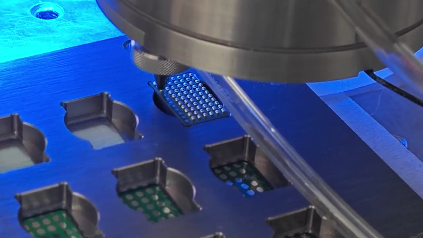
The supplied footage shows 0.25 mm solder ball processing on a 0.4 mm pitch test pattern. It is useful as a description of that demonstration and no more. It does not define a minimum ball size, a minimum pitch, a boundary that applies to every design or an outcome for a customer workpiece. It also does not establish a comparison result against hand soldering. A joint that looks similar in a photograph may differ in its accessible position, its fixture presentation, its datum or its customer-defined acceptance criteria. The appropriate use of the frame is therefore limited: it can help explain the documented process context and identify a possible discussion point for a proposed application. The next step is not to extrapolate the footage into a capability promise. It is to compare the actual target with the test arrangement, define the fixture and reference plan, and evaluate a representative sample. This distinction keeps test-pattern evidence from being represented as a product-specific production claim.
Plan a comparison around representative samples
A sample plan converts a method discussion into an evaluable question. Begin with representative workpieces and a clear statement of the target positions. Record the candidate laser arrangement: the individual solder-ball input under consideration, the fixture, datum, motion relationship, whether vision is to be evaluated and the selected configuration information. Then record the hand-soldering arrangement with enough detail to show how it will address the same target under the same acceptance criteria. The customer-defined criteria should be established before conclusions are drawn, so that the outcome is reviewed against a known basis rather than against an assumed general standard. The documented process footage and supplied images can provide context for the laser sequence, but they are not customer cases, production-yield evidence, qualification evidence or proof of material compatibility. Likewise, a sample observation should be described as evidence from the conditions that were actually evaluated. If the part, fixture, datum, position, candidate ball or acceptance requirement changes, the earlier observation should not be extended automatically to the changed arrangement.
Use a decision record rather than a general claim
The final comparison can be concise when the underlying record is complete. State the joint or positions assessed, the workpiece presentation, the reference approach, the laser process sequence and the information defined for the hand-soldering proposal. State whether optional vision was part of the laser evaluation. Identify the configuration references only as references for the documented system, and identify the customer-defined criteria used to review each sample. The decision can then say what was evaluated under those conditions and what remains to be evaluated if the application changes. This form of conclusion is more useful than describing either method as universally better for small joints. It preserves the difference between a documented system configuration and an application-specific result. It also gives later engineering discussions a usable starting point: a new target position, fixture change or altered reference strategy can be compared with the original record instead of being assumed equivalent. For small electronic joints, this traceable approach keeps the process choice connected to the real workpiece and the evidence available for it.