
Treat the fixture as part of the position-reference system
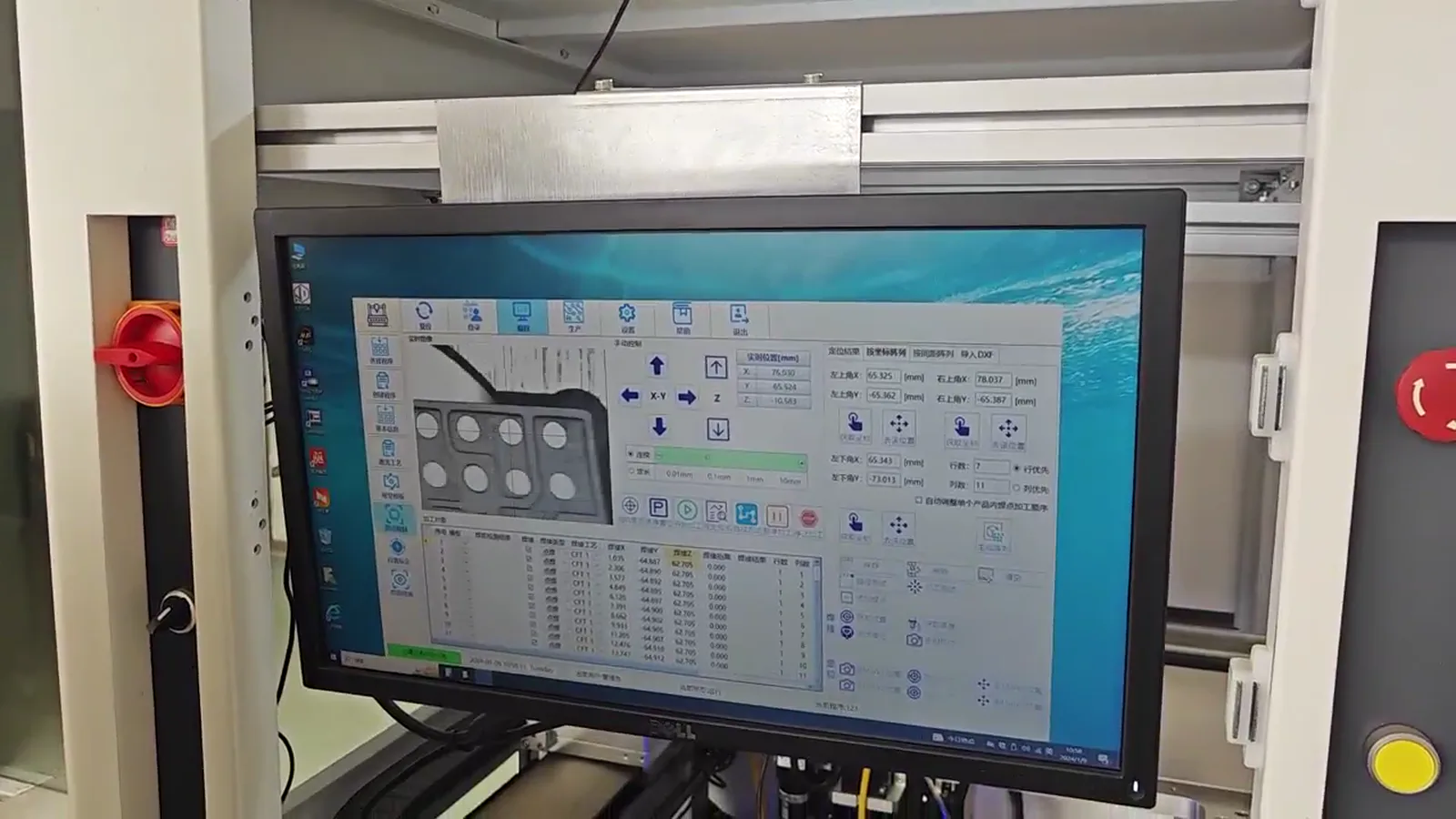
The fixture provides the starting relationship between the workpiece and the machine. A programmed coordinate has meaning only when the workpiece is presented in a known relationship to that coordinate. For this reason, fixture planning starts by identifying the intended soldering position, the direction from which the nozzle must approach and the physical reference that will define the part location. The supplied machine-operation frame shows fixture and work-area context, but it should not be read as an approved design for another component. A new fixture should be considered with the actual workpiece shape, the defined joint location, the available approach route and the customer-defined acceptance criteria. The engineering question is not whether a fixture exists; it is whether the fixture, reference and motion path define a repeatable position that can be checked on representative samples. Keeping these decisions together also avoids attributing a positioning result solely to the motion program or camera.
Choose a datum that represents the intended soldering location
A datum is the feature or relationship used to connect the workpiece to the programmed soldering position. It can be established by a defined part feature, a controlled fixture feature or a combination of both. The useful datum is not necessarily the most convenient edge to touch or image; it should have a meaningful relationship to the location receiving solder. During a review, document which surfaces or features establish the part location, the orientation of the part and what stops the part from being presented differently between placements. Then relate the chosen datum to each programmed soldering position. This makes it possible to distinguish a fixture-location question from a motion-coordinate question. If the reference does not represent the intended location, adjusting motion coordinates cannot prove that the workpiece itself is correctly presented. A defined datum strategy also gives sample evaluation a clear basis: the observed soldering result can be reviewed against the same reference used during setup rather than against an assumed nominal position.
Review support, retention and nozzle access together
Support and access are linked decisions. The workpiece must be held in the intended orientation while leaving the defined soldering location available to the nozzle. A fixture review should map the accessible space above and around the target, the expected nozzle route and the surfaces used to locate or retain the part. It should also identify whether the fixture itself could obstruct the nozzle approach, obscure a visual reference or make it difficult to confirm that the part is fully seated. These are design-review questions, not claims that one fixture arrangement suits every workpiece. A simple development fixture may be sufficient to assess part presentation and access, while another application may require a different level of fixture detail before a broader equipment concept is discussed. The important point is to evaluate the physical presentation that will actually be used. A clear view of an empty work area or a successful video sequence does not establish that a new workpiece will present its defined location in the same way.
Connect the mechanical reference to the programmed sequence
The fixture is useful only when its reference is connected to the motion sequence. First establish how the part is loaded and referenced. Next identify the coordinate relationship between that reference, the nozzle and every intended soldering point. Then review the order in which the points are processed and whether the part remains in its defined position throughout that sequence. In the documented process, the individual solder ball is separated, melted at the nozzle and moved by gas-assisted transfer toward a defined workpiece position. This makes the defined position a practical input to process evaluation, not a decorative drawing annotation. Record the fixture reference, the programmed location, the nozzle approach and any observation used to confirm the presentation. When a trial result is reviewed, these records help isolate whether a change concerns workholding, coordinate definition, access or the process condition. They also keep a maximum dot-frequency reference separate from the complete handling, positioning and evaluation sequence.
Use vision to address a defined variation, not by default
Optional vision can be considered when a visible feature needs to be located or when a defined placement variation must be evaluated. It does not replace the need to present the part consistently. The camera reference, lighting conditions, calibration relationship, fixture and motion coordinates must all connect to the same physical soldering location. A useful review first states what feature is to be found and why that feature is relevant to the target point. It then considers whether the fixture makes that feature available in the required view and whether the motion path uses the resulting reference in a defined way. The supplied documentation describes ±10 μm vision positioning for one system. That figure is specific to the described system and should not be carried into a different fixture, image condition or application as a general accuracy claim. A mechanical datum may be appropriate in one evaluation; a combined fixture-and-vision strategy may be appropriate in another. The choice should follow the actual positioning problem and representative sample evidence.
Develop the fixture through representative sample evaluation
A practical fixture-development cycle begins with information that makes the intended workpiece position visible: close views of the soldering location, drawings where available, the required orientation, access constraints, the intended point sequence and customer-defined acceptance criteria. The first fixture concept can then be used to assess how the part seats, how its datum is established and whether the nozzle can reach the defined location. During evaluation, keep the fixture arrangement and the reference method explicit in the record. If vision is included, record the feature used as the reference and the relationship being evaluated. If the fixture or reference changes, treat that as a change to the position-reference system rather than assuming the prior result transfers unchanged. Supplied process and CCD footage provides real context for discussing this workflow, and sample images can support process discussion. Neither is an approved customer case or evidence that a new component has been qualified. The appropriate conclusion is application-dependent: sample validation informs the next fixture decision, while final acceptance remains defined by the customer.
Keep documented configuration references in their stated scope
Documentation can inform the starting conversation, but its figures should remain tied to the configuration in which they were described. The supplied material shows approximately 0.2–0.9 mm solder ball application, up to 6 dots/s, 100/200 W laser configuration and ±10 μm vision positioning for one described system. These are configuration-dependent references, not a combined promise for every fixture, workpiece or process sequence. Up to 6 dots/s is not a complete cycle-time figure because a full sequence can include workpiece presentation, reference checking, motion and any evaluation steps. Likewise, a documented vision value does not determine the accuracy of a new fixture strategy. The supplied fine-pitch frame is limited to a demonstration of 0.25 mm solder ball processing on a 0.4 mm pitch test pattern only. It should not be used to claim a general minimum pitch, broad geometry capability or production result. Fixture and process decisions should follow the representative application and its acceptance criteria.