
Start with the joint and the acceptance criterion
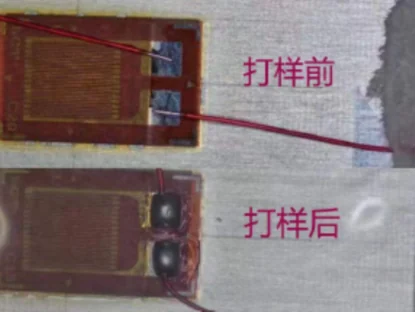
Before changing a parameter, define the observation precisely. Is the joint absent, displaced, irregular in outline, insufficiently connected, excessive in volume or simply different from the reference appearance? Record the part orientation, joint location, selected solder-ball condition, relevant recipe, fixture arrangement and inspection method. A visual difference may matter greatly in one assembly and be acceptable in another, so the customer’s drawing, specification or agreed sample criterion should remain the reference. Macro photographs and before/after comparisons are useful for discussion, but they do not by themselves establish electrical, mechanical or metallurgical qualification.
Defects are symptoms, not single-cause labels
The same visible result can have more than one possible cause. A displaced joint may reflect a position-reference issue, part movement, access limitation or an interaction between the nozzle path and the workpiece. An incomplete-looking joint may involve solder volume, surface condition, energy delivery or the actual geometry of the connection. For that reason, avoid treating a defect name as a machine setting. Compare a controlled sample with the process record and change one meaningful variable where practical, while keeping the component, fixture and inspection method identifiable.
A practical investigation table
The table is a starting framework for engineering review, not a fault code list. The relevant checks depend on the particular component, materials and process configuration.
Surface condition and solder volume
Wetting and final joint appearance depend on the surfaces presented to the soldering process. Review pad or terminal condition, contamination risk, finish information where available and any handling step that may have changed the surface. Also confirm that the selected solder-ball diameter is appropriate to the pad geometry, access and intended joint volume. The supplied documentation describes approximately 0.2–0.9 mm ball application for a documented configuration, while a supplied test-pattern frame demonstrates 0.25 mm ball processing on a 0.4 mm pitch test pattern. Neither reference is a universal minimum, maximum or recommendation for an unrelated component.
Energy, transfer and localized heat
A laser soldering result should be reviewed as a relationship between the solder ball, guide path, nozzle, laser energy, gas-assisted transfer and workpiece. If the solder does not form the intended joint, inspect the process sequence and the actual part rather than assuming that more energy is the answer. Nearby materials and sensitive features also belong in the review because a suitable localized process must be suitable for the complete assembly. Energy settings, laser selection and other operating values are configuration- and application-dependent; source values should not be copied into a different build without evaluation.
Positioning, fixture support and access
A well-defined position reference is central to a repeatable joint. Check whether the workpiece is seated consistently, whether the fixture supports the relevant area, and whether the programmed path reaches the target with an appropriate approach. Vision can help locate a defined feature, but it does not replace stable part presentation or calibration between the camera reference and the jetting point. The supplied source cites ±10 μm vision positioning for one documented system; that value must remain tied to its configuration and conditions. If a joint is consistently offset, compare the datum, fixture, motion path and nozzle relationship before changing solder material or appearance criteria.
Use sample evidence to decide the next action
After the initial review, separate observations from hypotheses. A useful record identifies the tested component, joint location, ball selection, fixture, process sequence, inspection method and result. Repeat the check with representative samples and the acceptance criterion that matters to the application. The result may be a parameter study, a fixture revision, a position-reference change, a surface-preparation review or a conclusion that the current process needs a different configuration. This evidence-led sequence is more reliable than claiming that a generic machine setting resolves every solder-joint defect.