
Treat geometry as the definition of the process window
A joint is not fully described by a single nominal point. Its evaluation begins with the features that establish where solder is meant to arrive and how the process head can reach that location. Useful geometry information includes the target position, the local outline of the joint area, neighbouring features, available clearance, intended approach direction and the way each part is located in a fixture. This information gives the delivery path a physical reference. It also prevents a general machine description from being mistaken for an application conclusion. In laser solder ball jetting, an individual ball is delivered and separated before laser energy melts it at the nozzle. Gas-assisted transfer then moves the molten solder toward the defined workpiece position. Whether that controlled sequence suits a particular geometry remains an application-dependent question. The geometry has to be reviewed with the actual workpiece presentation, the planned motion path and the customer-defined acceptance criteria. A drawing, close photographs and representative samples make that discussion more concrete than a generic request for a smallest size or a fastest setting.
Relate solder-ball selection to the receiving geometry
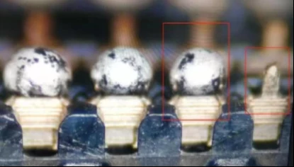
The solder ball is a discrete starting piece of solder, so its selection should be considered against the actual joint geometry rather than selected from an isolated headline figure. The receiving area, the desired visible joint outline, local clearance and nozzle access are all part of that comparison. Documentation for one configuration describes approximately 0.2–0.9 mm solder-ball application. This is useful context for an engineering conversation, but it is configuration dependent and is not a universal range, a recommendation for every workpiece or a definition of what another assembly will accept. The supplied process frame marked 0.25 ball and 0.4 pitch has a similarly narrow meaning: it demonstrates 0.25 mm solder-ball processing on a 0.4 mm pitch test pattern only. It should not be converted into an unspecified minimum, a broad pitch capability statement or a prediction for a different joint. The responsible next step is sample validation, with the selected ball evaluated alongside the real geometry, fixture and agreed inspection approach.
Nozzle access is a geometric question, not an afterthought
The nozzle must have a usable relationship to the intended workpiece position for the documented melting and transfer sequence to be evaluated. That makes access direction and surrounding clearance part of the design review. A target may appear available in a top view while the practical approach path is limited by nearby features or by the way the part must be supported. Conversely, an apparently compact joint may be straightforward to evaluate if its location can be presented consistently and the process head has a defined path to it. The review should map the target point, proposed nozzle approach, local obstructions and the fixture elements that are required to hold the workpiece. It should also establish whether every joint in a pattern can use the same presentation and reference logic. This does not prove a process result; it identifies the questions that a sample arrangement should answer. The documented gas-assisted transfer should be discussed within this complete geometry, rather than treated as an assurance that molten solder will reach any restricted location. When access changes across a part, the motion sequence and recipe may need to be assessed position by position.
Fixture, datum and motion form one reference chain
A machine coordinate has value only when it is connected meaningfully to the workpiece. Fixture support establishes how the part is presented; a datum defines the reference from which the target locations are understood; and motion brings the nozzle to the programmed relationship with those locations. These are not separate purchasing options. They are parts of the same reference chain and should be evaluated together with the joint geometry. For example, the review can identify the surfaces or features used to locate the workpiece, the direction in which it is held, the target locations relative to that datum and the motion path between them. The goal is not to assume a particular fixture design from an image, but to make the presentation repeatable enough to assess on representative samples. The fixture must also leave the joint area and nozzle approach available for the proposed process sequence. A stated motion routine alone does not establish that relationship. The relevant evidence comes from the configured fixture, datum definition and workpiece condition used in sample validation. Customer-defined acceptance criteria should determine what needs to be observed during that evaluation.
Use vision as a reference decision, where the geometry calls for it
Vision may be considered when an image-based reference is useful for relating the programmed process to the workpiece. It is not a substitute for the fixture or datum; it is evaluated with them. The image feature, camera-to-process relationship, fixture presentation and intended jetting point all belong in the same discussion. Documentation cites ±10 μm vision positioning for one described system. That value should remain attached to that described system and its conditions. It is not a universal positioning accuracy, and it does not by itself characterize the final relationship between nozzle and every customer workpiece. For a geometry review, the practical question is what feature can be used as a meaningful reference and whether it relates clearly to the joint target. If vision is not required, a stable fixture datum may be the appropriate point of evaluation. If vision is considered, sample validation can examine the reference strategy without making a general claim about all parts, patterns or acceptance requirements.
Build sample validation around the actual joint pattern
A useful sample evaluation starts by converting the joint layout into a short engineering checklist. Identify each target position, the available nozzle path, relevant clearance, the proposed ball choice, the fixture datum and whether an optional vision reference is to be assessed. Then define the intended sequence: individual-ball feed and separation, positioning, laser melting at the nozzle, gas-assisted transfer toward the target and movement to the next defined position. The checklist should also state what the customer will use to judge the samples. Visible joint appearance can support a review, but a supplied macro image is not a complete inspection result or a qualification record. The customer-defined acceptance criteria should therefore identify the observations, evaluation method and decision path required for that application. This approach keeps the trial focused: it asks whether the actual geometry, workholding and positioning concept can be evaluated with the selected configuration. It avoids treating a process video, a single demonstration frame or a nominal specification as evidence for an unrelated product. The result should be described as sample-specific evidence, with further configuration decisions following the application evaluation.
Keep documented values in their proper scope
Published technical values are most useful when they are read as boundaries for questions, not as a combined promise. Supplied documentation identifies 100/200 W laser configuration and up to 6 dots/s for described configurations. The frequency is a documented maximum, not a complete cycle-time statement: part presentation, fixture actions, motion travel, any vision step and inspection are separate elements of a full process sequence. Likewise, the 100/200 W reference is a configuration detail rather than a conclusion about an untested joint. Alongside the approximately 0.2–0.9 mm ball-application reference and the documented vision figure for one system, these values help frame a sample-evaluation discussion. They should not be combined into a universal machine specification or used to infer production outcome. For a geometry-driven evaluation, the decisive information remains the real joint layout, the proposed fixture and datum, access to each defined position, the selected test arrangement and the customer-defined acceptance criteria.