
Start with the process sequence, not the cell outline
The documented process has a clear physical order. One solder ball is fed and separated for the next operation. Laser energy melts the ball at the nozzle. Gas-assisted transfer then moves the molten solder toward the defined workpiece position. Inline planning should preserve this sequence as the basis for every upstream and downstream decision. The part must arrive in a condition that allows its intended position to be established; the process head must reach the programmed locations; and the completed part must leave the station according to the agreed flow. Drawing a conveyor, an enclosure or a loading concept before the workpiece reference is understood can hide the actual engineering question: whether the joint, fixture and position strategy can work together on representative samples. Automation should therefore be discussed after the soldering action and workpiece presentation have been described clearly. It is a way to organize a demonstrated process, not evidence that an unspecified product is suitable.
Define what the fixture has to establish
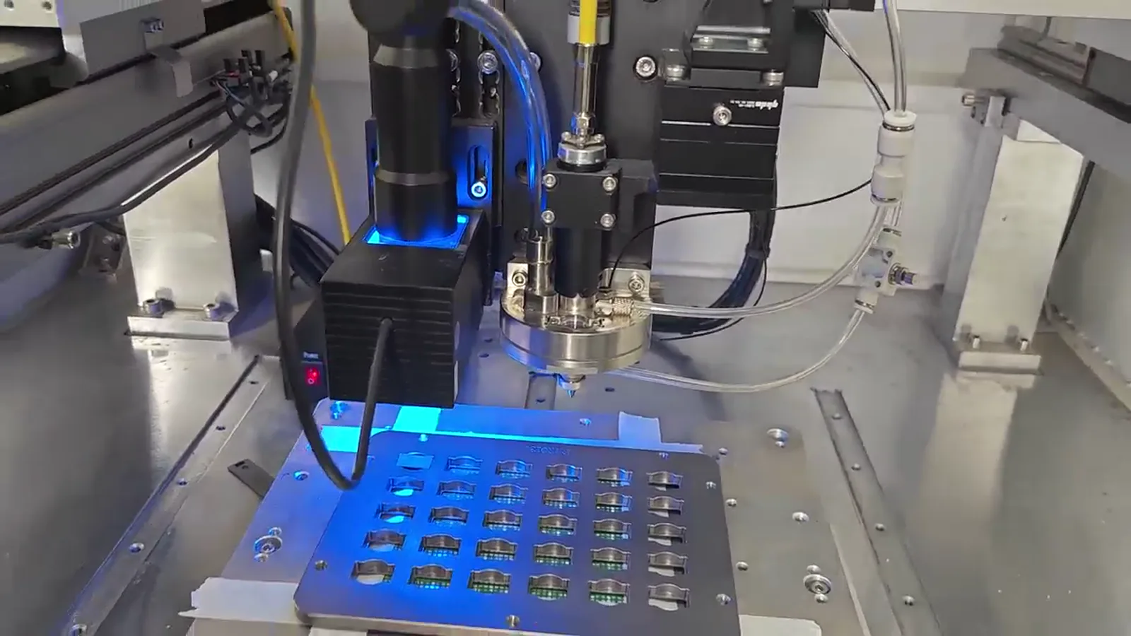
A fixture is more than a holder at the side of a nozzle. Its role in this evaluation is to support the workpiece and establish a meaningful mechanical relationship between the part and the process location. That relationship should be considered alongside the intended datum, the available nozzle approach and the motion path. A fixture concept may be simple where the workpiece can be presented consistently, or it may need further development where the reference is unclear. In either case, it should be evaluated with the actual workpiece condition rather than inferred from a general machine image. The supplied machine-operation frame shows a precision soldering system working around a fixture, which is useful context for the relationship being discussed. It is not an approved customer case or a general fixture specification. The acceptance criteria for a sample evaluation should state what the fixture must enable the team to assess, rather than assume a result from the frame alone.
Treat motion and datum as a single reference chain
Motion can bring the nozzle to programmed positions, but coordinates become useful only when they are related to the workpiece. The datum strategy connects the programmed path to the part that is held in the fixture. In an inline concept, the team should consider how that relationship is established at the station, how the workpiece is presented to the fixture, and which joint positions are to be addressed in sequence. These are application-dependent questions; there is no general motion path that proves suitability for every workpiece. The review should also distinguish the soldering action from the complete automated sequence. A stated rate at the nozzle is not a complete station cycle. The source material documents up to 6 dots per second for a described configuration, but that is a configuration-dependent maximum dot frequency, not a commitment for loading, placement, motion travel, position reference or any other part of an inline flow. A customer-defined sequence and representative samples are needed before discussing the usable process timing.
Add vision only where it serves the real reference problem
Vision may be evaluated when an image-based reference is useful for the workpiece and the defined soldering positions. It should not be treated as a substitute for fixture support or datum design. Camera information must still be connected to the workpiece reference, the motion coordinates and the physical location at which the molten solder is transferred. The supplied documentation identifies plus or minus 10 micrometres of vision positioning for one described system. That number belongs to that described system and its conditions; it is not a universal application accuracy, a guaranteed placement result or a statement about a complete automated cell. For an inline evaluation, the appropriate question is whether a vision step contributes meaningful confirmation or reference for the intended part presentation. If it does, the resulting strategy should be assessed together with the fixture and motion arrangement on representative samples. If the fixture datum already supplies the necessary reference, vision may not be the central decision.
Use configuration information in its proper scope
Technical values help frame a process discussion only when their scope stays intact. Supplied documentation describes approximately 0.2 to 0.9 millimetre solder-ball application, up to 6 dots per second, plus or minus 10 micrometres of vision positioning for one described system, and 100 or 200 watt laser configuration. These references should not be combined into a universal machine specification, an inline production promise or a selection rule for an unknown workpiece. Ball application is evaluated with the defined process position and sample result; the documented dot frequency is not total cycle time; the positioning reference remains connected to its system; and laser configuration is application dependent. The supplied process footage also includes a 0.25 millimetre solder ball processed on a 0.4 millimetre pitch test pattern. That frame establishes only that demonstration. It does not establish an unspecified minimum, a general pitch capability or performance on another part. Keeping each fact within its documented context produces a more useful engineering discussion than extending it into a broad claim.
Build sample validation into the automation decision
Sample validation should link the proposed automation arrangement to customer-defined acceptance criteria. First, identify the workpiece positions to be addressed and the reference that will define them. Next, evaluate the fixture, motion and any vision step together while the documented ball-feed, laser-melt and gas-assisted-transfer sequence is applied toward those positions. The result can be reviewed against the acceptance criteria agreed for the application. This approach keeps the evaluation specific: a visible result from supplied process video or sample imagery provides process context, not a customer result, production qualification, reliability conclusion or universal approval. It is also useful to separate an early sample setup from a final automation discussion. An early fixture and program can answer whether the workpiece can be presented and addressed for evaluation. A later inline concept can then be defined around the same proven reference logic, provided that the desired handling and sequence are also examined. Final configuration follows the application review and sample validation.
Prepare an inline review with decision-ready information
An efficient review describes the defined workpiece positions, the intended process sequence and the information needed to judge the reference chain. Share representative samples and available views or drawings that make the soldering locations and fixture relationship understandable. Identify the number and order of positions to be evaluated, the available approach for the process head, how the part is expected to be presented at the station, and the customer-defined acceptance criteria. If vision is being considered, identify the feature or reference that is intended to support the position decision. If timing matters, describe the desired handling sequence rather than relying on the maximum documented dot frequency. The discussion can then focus on the real choices: how one ball will be delivered to each defined location, how the workpiece will be supported, how the datum and motion will relate to it, whether vision adds value, and what the sample evaluation must show. That is the appropriate basis for an application-dependent inline automation concept.