
Start with the documented process sequence
The process begins when a solder ball is fed to the head and separated as an individual ball. Separating one ball establishes the discrete solder input for the next operation; it does not by itself define whether that input is appropriate for a particular joint. At the nozzle, laser energy melts the ball. Gas-assisted transfer then moves the molten solder toward the defined workpiece position. Motion proceeds according to the selected sequence, while fixture support and the selected datum establish how the workpiece is presented to that sequence. This order is a useful way to organize a parameter review. First ask how one ball reaches the nozzle. Then ask how the workpiece location is defined. Next evaluate melting and transfer on representative samples, and finally review the observed result against customer-defined acceptance criteria. Treating the operation as a chain avoids assuming that a setting at one stage can compensate for an unresolved issue elsewhere in the chain. For example, a software coordinate needs a reliable physical reference, and a visible sample is evidence of that sample rather than a general conclusion about another design.
Ball application is a joint-specific input
A solder ball is the starting solder input for an individual jetting event. Its selection should therefore be discussed in relation to the specific workpiece position and the result the customer needs to evaluate, not as a generic machine setting. Supplied documentation describes approximately 0.2–0.9 mm solder ball application for a documented configuration. This is useful scope information for an initial discussion, but it is not a universal machine limit, a recommendation for every assembly or a statement of what another component will accept. The right evaluation uses the actual part, its accessible soldering position, the fixture approach and the customer-defined acceptance criteria. A supplied process frame also shows 0.25 mm solder ball processing on a 0.4 mm pitch test pattern. The frame establishes only that demonstration. It does not establish a minimum pitch, a minimum ball size, a capability boundary for all designs or a result on a customer product. When ball information is carried into an application review, the responsible question is whether the proposed ball and the intended workpiece should be tested together.
Laser configuration must remain configuration-dependent
Laser energy performs the melting step at the nozzle, but a laser configuration is not a self-contained process recipe. The supplied documentation identifies 100/200 W laser configuration for a described system. That information should remain attached to the documented configuration and should not be converted into a universal power claim, a required setting or an assurance that an unrelated part can be processed in the same way. In practical process evaluation, the laser configuration belongs beside the individual ball, nozzle-based melting location, gas-assisted transfer, workpiece presentation and planned sequence. Representative sample work provides the place to observe the process under the selected configuration and to compare the outcome with the agreed evaluation criteria. It is also important to distinguish configuration information from an application result. A stated 100/200 W configuration tells a reader what is described for one system; it does not document a parameter set for every job. Recording the system configuration and the sample conditions keeps future discussion tied to what was actually evaluated rather than to an isolated headline value.
Position is a reference-chain parameter
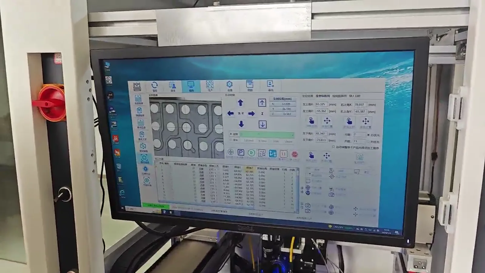
The soldering position is defined by more than the programmed motion point. The workpiece must first be presented by a fixture and related to a meaningful datum. Motion then takes the process head through the intended sequence. Optional vision can be considered where an image-based reference is needed, but vision should be evaluated with the fixture, datum and motion rather than treated as a separate guarantee. The supplied CCD interface is useful visual context for this kind of positioning and recipe discussion; it is not evidence of a customer case or a qualification result. The supplied documentation cites ±10 μm vision positioning for one described system. That figure must remain limited to that system and its associated configuration, image conditions, datum strategy and application context. It is not an accuracy promise for every workpiece or fixture. A sound review asks what physical feature defines the position, how the fixture presents that feature, whether optional vision can use that reference as intended, and how the resulting position relates to the nozzle. Those questions are answered through process evaluation and sample validation, not by transferring a vision number from another setup.
Gas-assisted transfer completes the localized event
After the ball is melted at the nozzle, gas assistance transfers the molten solder toward the defined workpiece position. This transfer is a distinct part of the documented process and should be evaluated as part of the same sequence as feeding, separation, melting and positioning. It is not enough to describe the laser source without considering how the molten solder is moved from the nozzle toward the target. Nor is it appropriate to infer an unprovided gas setting, gas effect or process outcome from the existence of gas-assisted transfer. The supplied facts support a careful description of the sequence, not a universal claim about material behavior, reliability or compatibility. For an application review, the practical task is to establish the target position, fixture and datum; run a representative sample under a selected configuration; and review the result using criteria defined for that application. If the process contains multiple positions, the transfer event must be considered within the planned path rather than as an isolated demonstration. The resulting evaluation can remain traceable to the particular sample, configuration and acceptance requirement instead of being overstated as a general production conclusion.
Dot frequency is not complete cycle time
Supplied documentation states up to 6 dots/s for a described configuration. This is a dot-frequency reference, not a complete production-cycle commitment. A full sequence may include individual-ball feed and separation, motion between positions, fixture actions, datum establishment, optional vision activity and any review steps selected for the application. The relative contribution of those actions depends on the selected workpiece setup and sequence, so it should not be replaced by a single throughput statement. The useful engineering use of the documented figure is to identify one element for evaluation: the possible frequency of the described dotting operation. The complete timing question remains application-dependent. During sample validation, the planned sequence can be made explicit: when the part is presented, how its reference is established, which positions are processed, and what happens before the next part or cycle. This keeps a later cycle-time discussion rooted in the actual operation rather than in a demonstration rate. It also prevents a technical document from suggesting that an individual dot rate guarantees system-level output.
Build a parameter review around sample validation
A useful review begins with information that describes the particular task: a clear view of the target workpiece position, a proposed datum, the intended fixture concept, the required motion sequence, whether vision is to be evaluated, and the customer-defined acceptance criteria. The process discussion can then connect those inputs to individual-ball feed and separation, nozzle melting, gas-assisted transfer and the selected configuration. Representative samples are important because they turn general process information into evidence from the actual application. They also help keep the scope of any conclusion clear. Supplied process and CCD footage can explain the machine and positioning context, while supplied sample imagery can support discussion of visible results. None of those assets are approved customer cases, company photographs, brochures or proof of universal production qualification. A responsible conclusion is therefore limited to what was evaluated on the supplied sample under the chosen configuration. If the application changes, the fixture, datum, ball selection, motion plan or acceptance criteria may need to be reviewed again. Final configuration should follow application evaluation and sample validation.