
Pitch is a pattern input, not an isolated capability claim
For a repeated application pattern, pitch describes the planned spacing relationship between intended workpiece positions. That input is important because the process must address each location in the pattern, yet the pitch value by itself leaves many essential questions unanswered. It does not identify how the workpiece is held, what feature establishes the location, how the programmed motion relates to that feature, or whether vision is being considered for the application. It also does not turn a demonstration on one test pattern into a general limit for another layout. A useful review therefore starts by documenting the actual position pattern and the workpiece reference available to it. The goal is not to label a spacing as inherently easy or difficult. The goal is to determine what must be evaluated for that spacing on the intended workpiece. This approach keeps the discussion tied to a defined process position and avoids treating a single number as a universal production specification. Where the layout includes several locations, it is also useful to identify the sequence in which those locations are to be evaluated, rather than assuming that every position has the same practical context.
Read pitch through the documented jetting sequence
The documented sequence gives the pitch review a clear physical context. An individual solder ball is first fed and separated. Laser energy melts the ball at the nozzle. Gas-assisted transfer then moves the molten solder toward a defined workpiece position. Pitch concerns the relationship between those defined positions, but the result of the review depends on the complete sequence rather than on spacing alone. The nozzle and workpiece relationship, the part presentation and the motion plan should be described alongside the location pattern. Doing so makes it possible to ask bounded questions: Which feature identifies the target position? What establishes the workpiece reference before the sequence begins? Which motion steps bring the nozzle to the planned locations? Is vision part of the proposed locating approach? These are questions for process evaluation, not statements that a particular pattern will work. Supplied process videos and images can help explain the sequence, but they do not qualify an unrelated workpiece. A sound article, enquiry or test plan should keep the documented mechanism distinct from the evidence needed for the customer’s own pattern.
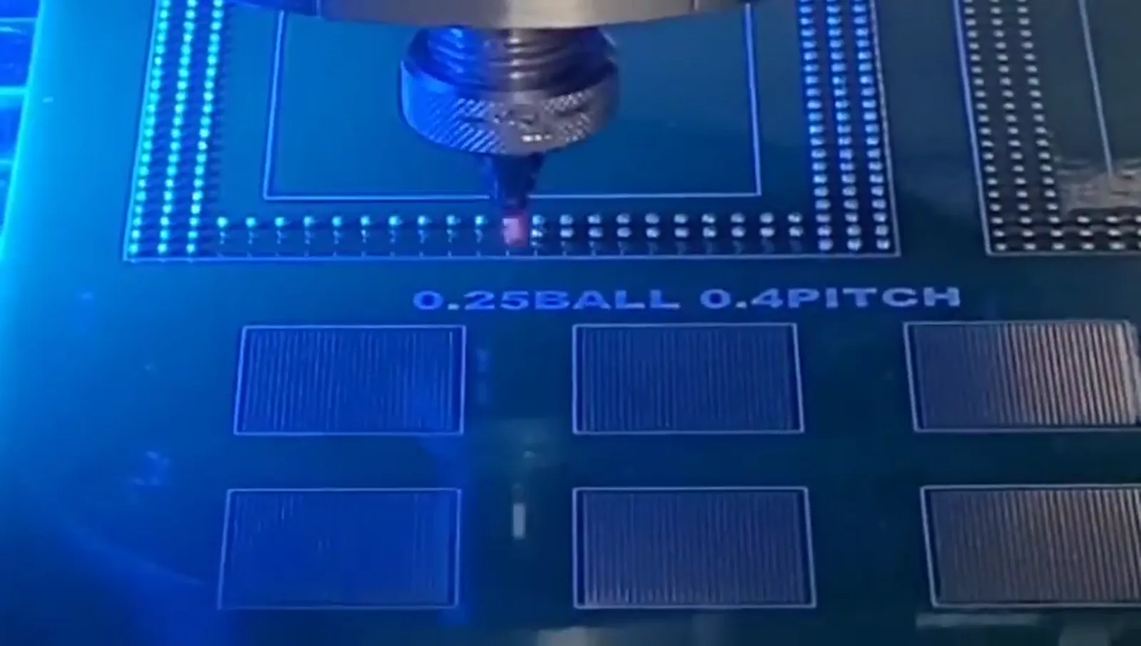
Keep the 0.25 mm ball / 0.4 mm pitch frame in its stated context
The supplied frame is marked for 0.25 mm solder ball processing on a 0.4 mm pitch test pattern. That is the full, supportable reading of the visual evidence: it demonstrates 0.25 mm solder ball processing on that named test pattern. It should not be restated as a universal minimum pitch, an equipment guarantee, a production qualification or a finding about another part. In particular, the frame does not provide approval of a customer layout that happens to use the same nominal pitch. A test-pattern image shows one supplied condition, not the fixture, datum, motion arrangement, acceptance criteria or sample observations required for a separate condition. It is appropriate to use the frame as a reference when explaining why fine position patterns deserve careful review. It is not appropriate to use it to infer a broader boundary. For an actual project, document the proposed pattern independently, then compare it with representative sample evidence generated for that project. This distinction protects both the value of the supplied demonstration and the integrity of an application-dependent recommendation.
Evaluate fixture, motion and datum as one location system
A defined workpiece position does not arise from motion alone. The fixture presents the workpiece, the datum identifies the reference from which positions are interpreted, and the motion plan carries the process through the planned pattern. These elements should be evaluated together because a pitch request is ultimately a request to address multiple defined locations in relation to the same workpiece. Vision may be considered where it is relevant to the locating strategy, but it should be reviewed in the context of the fixture, datum and motion rather than treated as a separate universal answer. The supplied documentation cites ±10 μm vision positioning for one described system. This figure must remain attached to that described system and its configuration; it does not define the position result for every setup or workpiece. A practical evaluation can state the selected fixture concept, the datum to be used, the intended motion sequence and whether vision is proposed. It can then test those choices on representative samples against customer-defined acceptance criteria. That produces an application-specific finding instead of an unsupported claim based on pitch alone.
Separate ball size from pitch, then review their interaction
Ball size and pitch are different inputs. Ball size describes the supplied solder-ball condition, while pitch describes the relationship between planned application positions. Both belong in the same review, but neither should be used as a shortcut for the other. The supplied documentation describes approximately 0.2–0.9 mm solder-ball application for a documented configuration. This is a configuration-dependent reference range, not a universal range for every machine, workpiece or process. It does not establish what ball condition should be selected for a particular pattern. Similarly, the 0.25 mm ball / 0.4 mm pitch frame identifies one demonstrated pairing only. An evaluation should record the intended ball condition and the intended position pattern separately, then consider them with the fixture, datum, motion and any proposed vision approach. This keeps the input set clear. It also prevents a reader from converting a range, an image caption or a sample result into a broad claim about performance. The appropriate conclusion is a scoped one: the stated condition has been reviewed or sampled under stated conditions, subject to the applicable customer-defined criteria.
Treat documented rate, laser and vision figures as configuration-scoped references
Several supplied figures can inform an early technical conversation, provided their limits are stated plainly. Documentation shows up to 6 dots per second, a 100/200 W laser configuration, and ±10 μm vision positioning for one described system. Each is configuration dependent. None should be combined into a promise about an actual application, and none by itself answers whether a particular pitch pattern is suitable. A dot-rate figure does not define the complete timing of a customer process. A laser configuration listing does not identify the setting for a particular workpiece. A vision-positioning figure for one system does not replace evaluation of a separate fixture, datum and motion arrangement. The engineering use of these figures is therefore descriptive rather than predictive: they identify items to clarify during configuration review. A responsible proposal can discuss which documented references are relevant, what remains to be evaluated, and what sample observations will be needed. It should not derive yield, reliability, total throughput, accuracy or production qualification from these figures.
Use sample validation to turn a pitch question into a bounded finding
Sample validation provides a disciplined way to assess a proposed position pattern without making universal claims. Begin with representative workpieces or a representative test arrangement, a documented pitch pattern, the intended solder-ball condition, a fixture concept, a stated datum and the planned motion and vision approach. Before the evaluation, agree the customer-defined acceptance criteria that will be used to judge the sample. During the review, retain a clear record of the stated configuration and the observations for the tested condition. The result can then be described precisely: it is evidence from that sample evaluation under those stated conditions. If additional pattern variants, workpiece presentations or acceptance criteria are introduced, they should be evaluated as additional conditions rather than assumed to follow from the first result. This method is useful whether the requested pattern is simple or closely spaced because it preserves the link between the workpiece, the location system and the acceptance decision. It also makes communication more practical: an engineering discussion can focus on the information needed for the next sample rather than on unsupported universal specifications.