
Start with the defined location, not a generic size label
A small-pad or confined-area request should begin by making the intended soldering location visible. A close image, drawing where available, or clear marked-up view can identify the target position and the features around it. The review can then distinguish the target from nearby geometry, fixture features, or other locations in the planned sequence. This is more useful than treating the word "small" as though it supplies a complete process definition. It does not establish a ball selection, an allowable spacing, a laser setting, a timing result, or a qualification decision. Instead, it prompts specific questions. What physical feature represents the target location? From which reference will the location be interpreted? How will the workpiece be presented? What space is available for the nozzle relationship and programmed motion? Which result will be assessed on a sample? Keeping these questions explicit prevents a nominal pad description from being mistaken for evidence of suitability. It also makes comparisons between samples more meaningful, because each sample can be discussed against the same marked position and stated arrangement. The requested process does not eliminate the need for this definition: the molten solder is transferred toward a defined workpiece position, so the definition of that position belongs at the beginning of the engineering discussion.
Read confined access through the documented jetting sequence
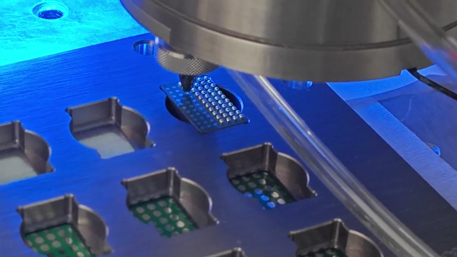
The documented sequence provides a disciplined way to review a restricted location. One solder ball is fed and separated from the next. Laser energy melts that ball at the nozzle. Gas-assisted transfer then moves the molten solder toward the defined position. Each step should be kept in its stated role. Feeding and separation describe the individual-ball starting condition; melting occurs at the nozzle; gas-assisted transfer describes movement toward the target. The sequence should not be expanded into claims about an unrelated joint, surrounding material, thermal response, or final production performance. For a confined area, the engineering review can map the planned relationship among the nozzle, the workpiece, and the target position at the moment the process is performed. It can also identify whether the planned path needs a clear approach route and whether the fixture permits the intended presentation. These are application questions, not implied proof that every restricted location can be addressed. A supplied close-up process frame can help explain the physical context of a jetting head over supported test positions. It cannot establish nozzle access, final location, or suitability for another workpiece. The correct conclusion remains bounded: the sequence is understood, while the actual location and arrangement need representative evaluation.
Treat fixture, datum, and motion as one position-reference system
A programmed position has practical meaning only in relation to the presented workpiece. The fixture provides support and a presentation relationship. The datum identifies the feature or relationship from which the intended location is interpreted. Motion connects that reference to the programmed sequence. For small pads and confined positions, these elements should be considered together before a sample is judged. A review can document how the part is loaded, what feature establishes orientation, what holds the workpiece in its intended relationship, and how the defined soldering position is connected to the motion plan. This does not require an assumption that one datum style or fixture arrangement is correct for every part. A useful datum is simply one whose relationship to the intended location can be stated and evaluated. If the fixture arrangement changes, the datum changes, or the workpiece presentation changes, that is a change to the position-reference system, not merely a minor visual difference. Recording the arrangement used for a sample helps keep the observed result connected to the actual condition. It also avoids assigning a positioning outcome to motion alone when fixture presentation or datum definition may be part of the same question. For a restricted location, the fixture must be reviewed for both its reference role and its relationship to the planned work area.
Review access and workpiece presentation together
A confined location should be reviewed in the presentation that will actually be evaluated, not as an isolated image of a pad. The fixture, supported part, selected datum, and planned motion form the context in which the nozzle relates to the defined position. A practical review can ask whether a fixture feature, support arrangement, or the workpiece itself changes the available path or obscures the feature being used as a reference. It can ask whether the workpiece is consistently presented before the sequence begins and whether the intended position remains defined as the planned locations are addressed. These questions help organize an evaluation; they do not prove that any particular geometry has been accepted. The aim is to make the position-reference system inspectable. For example, an evaluation record can show the marked target location, the fixture relationship, the workpiece orientation, the selected datum, and the proposed order of positions. This creates a traceable basis for discussing the condition tested. It is important not to infer broader conclusions from a clear view of one work area or a video of one operating condition. A new part can have a different available reference, support requirement, or path relationship. The part-specific presentation must therefore be considered before the scope of a system or sample result is described.
Use vision as an optional part of the locating strategy
Vision may be considered when a visible feature is relevant to locating the defined position. Its role should be stated in the same plan as the fixture, datum, and motion rather than described as a separate answer to every small-pad request. A review can identify the feature to be located, explain how that feature relates to the intended soldering position, and record the fixture and workpiece presentation used while the feature is viewed. The supplied documentation states ±10 μm vision positioning for one described system. This is a configuration-dependent reference for that described system, not a universal accuracy value for every part, camera condition, fixture, or motion arrangement. It should not be converted into a claim about a different confined-area application. In some evaluations, a mechanical datum may define the relevant relationship; in others, an optional vision strategy may be included. The appropriate approach follows the actual workpiece and the condition being evaluated. Where vision is used, it is useful to keep the observed reference feature and its relationship to the sample target in the record. That makes the locating approach clear without suggesting that an image alone qualifies the workpiece or replaces the need for a defined fixture and motion relationship.
Keep ball, rate, laser, and fine-pitch references in their stated scope
Supplied figures can inform a technical discussion when they remain connected to the configuration in which they were described. The documentation refers to approximately 0.2–0.9 mm solder-ball application, up to 6 dots per second, and a 100/200 W laser configuration. These are configuration-dependent references. They should not be assembled into a single promise for a specific small pad, restricted area, fixture, or workpiece. The ball-application range does not select a ball for another joint. The dots-per-second figure does not define complete process time. The laser configuration does not identify a setting or an outcome for another application. Likewise, the supplied 0.25 mm ball / 0.4 mm pitch footage is a test-pattern demonstration only. It demonstrates that stated condition and no more. It is not a general minimum pitch, a claim about every 0.25 mm ball condition, or evidence of production qualification for a different layout. Keeping each reference separate preserves its useful context and prevents a reader from turning documentation into an unsupported universal specification.
Build a bounded sample review for the actual confined location
Representative sample evaluation is the appropriate way to turn a confined-area question into a limited engineering finding. Prepare the information that defines the test condition: the intended soldering location, available images or drawings, the proposed fixture and datum, the workpiece orientation, the planned motion relationship, and whether vision is to be considered. State the individual solder-ball condition proposed for the evaluation without treating a documented range as a selection rule. Before judging the sample, identify the customer-defined acceptance criteria that will be used. During the review, record the actual arrangement: which location was evaluated, how the part was supported and referenced, and which configuration-dependent references were relevant to the discussion. The resulting observation can then be described accurately as evidence from that stated sample condition. It does not automatically apply if the pad layout, workpiece presentation, fixture, reference feature, motion plan, or acceptance criteria change. This disciplined scope is particularly useful for small pads because it keeps the discussion focused on the physical location rather than on a broad label. It also gives the next engineering discussion a clear basis: clarify what has been seen on the defined sample and what another condition would need to evaluate independently.