
Evidence-aware technical article
What Is Laser Solder Ball Jetting?
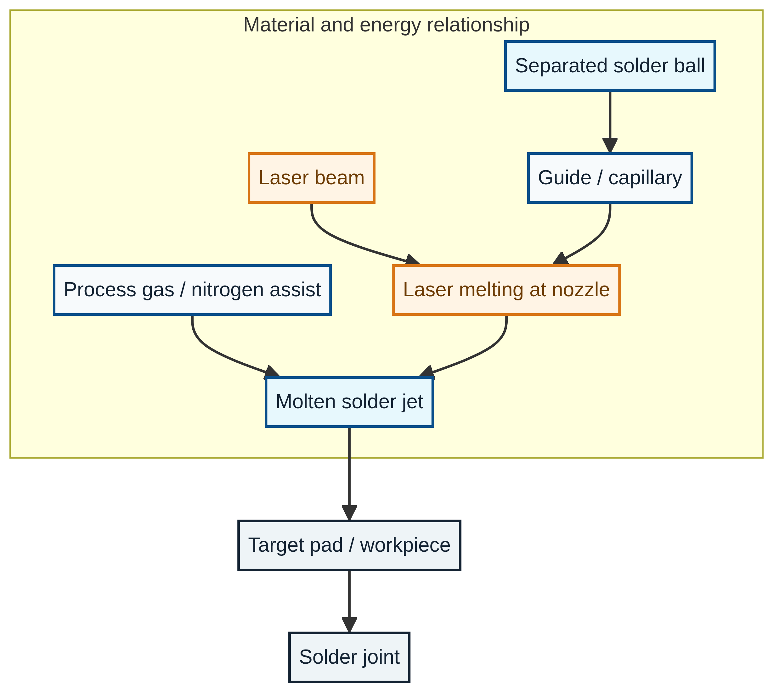
Laser solder ball jetting is a precision soldering process in which individual solder balls are fed through a guide path, melted by laser energy at the nozzle and transferred toward a defined soldering position with gas assistance. It is best understood as a coordinated process system—not simply as a laser source. Ball delivery, nozzle condition, energy control, motion, fixture design, positioning and inspection all affect how the process should be evaluated for a particular electronic assembly.
Process map
See the sequence before reading the detailed engineering questions
The full-width process map makes the transition from a visual overview to the deeper technical sections easier to follow. The supporting text remains live HTML throughout.

The basic sequence
The basic process sequence
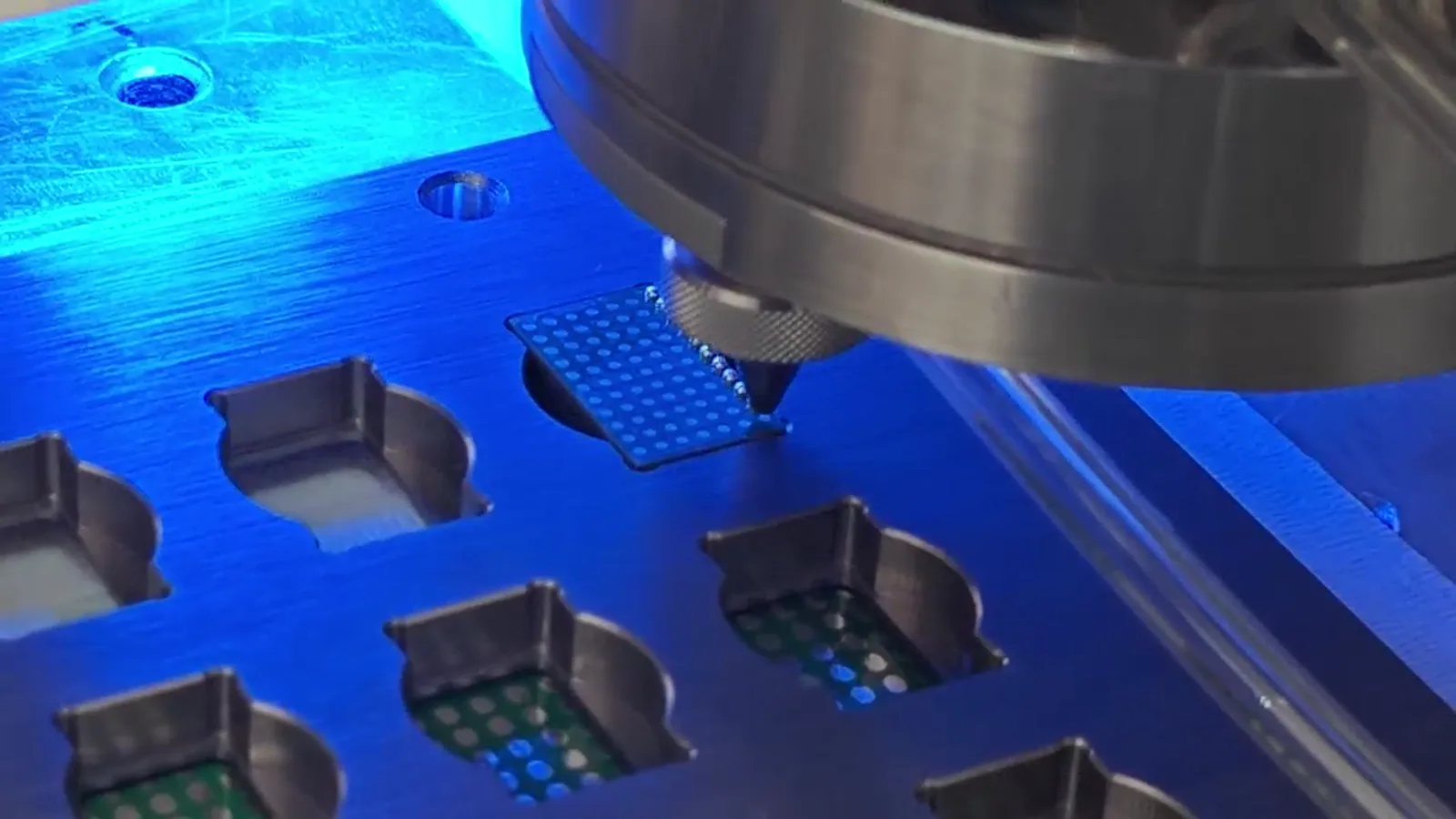
The documented sequence starts with solder-ball feeding and individual-ball separation. A controlled feed presents a ball to the process head, and the guide channel establishes its relationship with the nozzle. Programmable motion then brings the head and workpiece into the intended position. At the nozzle, laser energy melts the ball; gas-assisted jetting transfers the molten solder toward the target location, where the localized process forms the joint. The sequence continues according to the programmed path and any inspection or next-cycle logic. Each step matters: a stable laser setting cannot compensate for poor part support, and a repeatable motion path cannot by itself establish a suitable solder joint.
Material input and geometry
Why the solder ball is delivered separately
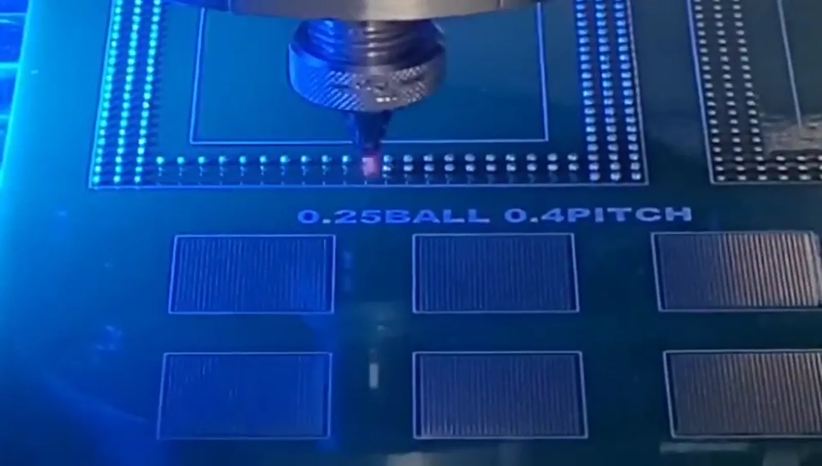
A solder ball provides a defined starting piece of solder for the process, while the appropriate diameter remains a joint-design decision. Pad dimensions, lead or terminal shape, surface condition, clearance, access and the desired joint appearance should be reviewed together. The source describes approximately 0.2–0.9 mm ball application for a documented configuration; that range should not be treated as a universal machine limit or a recommendation for every component. The supplied array-processing footage also shows a test pattern marked 0.25 BALL / 0.4 PITCH. Its factual meaning is limited to a demonstration of 0.25 mm solder ball processing on a 0.4 mm pitch test pattern, not a universal minimum pitch claim.
Energy and transfer
Laser melting and gas-assisted transfer
Laser energy is directed to melt the ball at the nozzle, after which gas pressure assists transfer to the soldering position. This localized action can be considered when the process must address a defined joint without treating the whole assembly as the soldering target. The actual thermal response still belongs to the component, pad, surrounding materials, fixture and selected process condition. The source identifies 100 / 200 W laser configuration in a documented system, but that reference is configuration-scoped rather than a promise that every build uses the same laser. Process development should therefore observe representative samples instead of inferring suitability from a power value alone.
Positioning and evidence
The physical process, reference chain and sample review must remain connected
The photographs are supplied process and sample context. They explain the discussion but do not become customer proof, a qualification result or a universal performance statement.
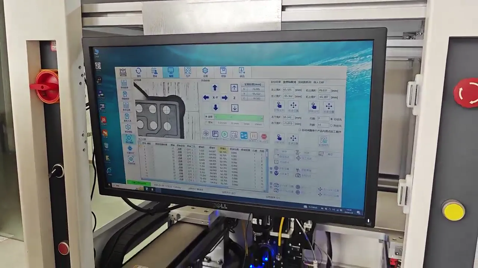
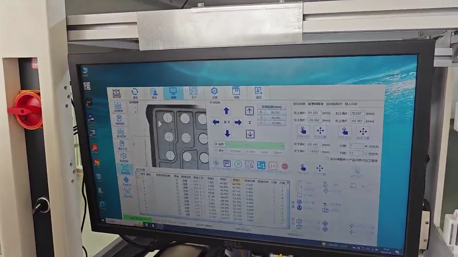
Vision reference context; fixture, datum and calibration still determine the final relationship.
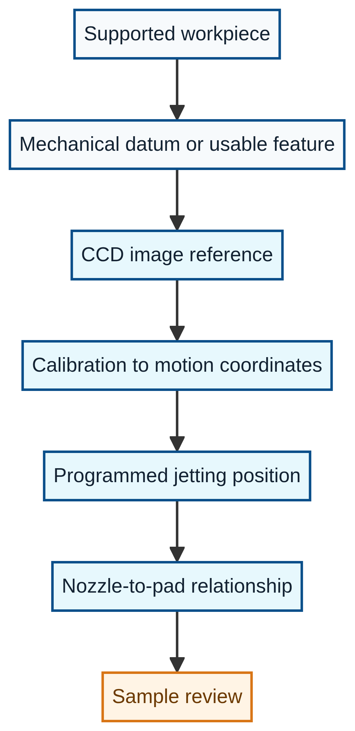
The diagram frames the reference chain without establishing a project-specific accuracy claim.
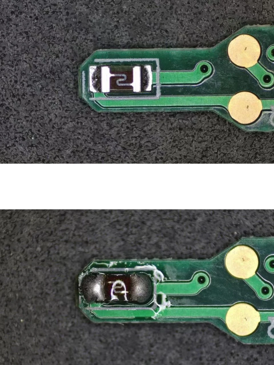
Supplied sample imagery can support a visible-review discussion but does not establish qualification.
From process explanation to evaluation
The later questions matter as much as the visible soldering event
The long-form guidance stays accessible as normal HTML while the image-led chapters prevent the technical article from becoming an uninterrupted wall of text.
- 04
Positioning, fixture and vision are part of the process
The jetting point only has meaning when its relationship to the workpiece is controlled. A fixture may provide the mechanical datum and support needed to hold the part; programmable motion defines the path; and vision can be used where image-based reference or correction is required. Camera, lighting, field of view, calibration, fixture repeatability and the physical relationship between the camera and jetting point all need to be considered with the real workpiece. The supplied documentation cites ±10 μm vision positioning for one described system. That figure must remain attached to its documented configuration and conditions, not presented as a universal accuracy for every application.
- 05
What the process can and cannot establish by itself
Laser solder ball jetting may be worth evaluating where localized solder delivery, controlled joint volume, restricted access or a programmable sequence are relevant engineering questions. It is not automatically a replacement for solder paste, reflow or hand soldering across all products. The correct comparison depends on the current method, joint geometry, thermal exposure, part presentation, inspection requirement and intended production flow. Likewise, a process video or a visible sample demonstrates process context, not customer ownership, production qualification or a guaranteed result on an unrelated design. A useful conclusion is specific to the tested component, selected ball, fixture, conditions and acceptance criteria.
- 06
How to begin an application evaluation
Start with the joint rather than a generic machine specification. Product photographs, drawings where available, pad or terminal information, material and surface details, current soldering method, joint count, access restrictions and the required quality criteria give the engineering review a usable basis. Representative samples allow the team to examine ball selection, workholding, position reference, laser and jetting conditions, joint appearance and the possible automation concept. The source notes a maximum frequency up to 6 dots/s for a described configuration; this is not a total cycle-time commitment because loading, clamping, motion travel, vision, inspection and unloading may govern the complete sequence. Final machine configuration should follow application and sample evaluation.
What each process element contributes
| Process element | Primary role | What still requires evaluation |
|---|---|---|
| Solder-ball feed and separation | Presents one ball through the guide path for the next cycle | Feed stability, ball selection and compatibility with the joint |
| Laser and nozzle | Melts the ball at the process head | Energy condition, work distance, material response and configuration |
| Gas-assisted jetting | Transfers molten solder toward the target position | Access, transfer behavior, surrounding features and joint result |
| Motion, fixture and vision | Relates the process head to the workpiece | Datum quality, calibration, repeatability and application-specific positioning |
| Inspection and recipe logic | Continues the programmed sequence and reviews the result | Customer acceptance criteria, path, handling and complete process flow |
Read this table as an application-evaluation framework, not as a universal equipment specification.
Visible FAQ
Practical questions after the technical overview
Use the article to prepare specific component, joint and process information—not a generic capability enquiry.
Is laser solder ball jetting the same as laser soldering with wire or paste?+
No. This process uses individually delivered solder balls, laser melting at the nozzle and gas-assisted transfer. Paste, wire and reflow processes have different material delivery and process sequences; the suitable method depends on the actual assembly and joint requirement.
Does the 0.25 mm ball / 0.4 mm pitch footage define a minimum capability?+
No. It is a supplied test-pattern demonstration of 0.25 mm solder ball processing on a 0.4 mm pitch test pattern. It should not be presented as a universal minimum pitch or a guarantee for another component.
What information is needed for a feasibility review?+
Send photographs, drawings where available, pad or terminal details, current process, access constraints, joint count and the required quality criteria. Representative samples are the most useful basis for evaluating ball selection, fixture, positioning and process conditions.
Have a micro-soldering application to evaluate?
Send the component information. Start with the process.
Share drawings, sample photographs or soldering requirements. The engineering discussion can connect the component to a suitable process and machine configuration.