
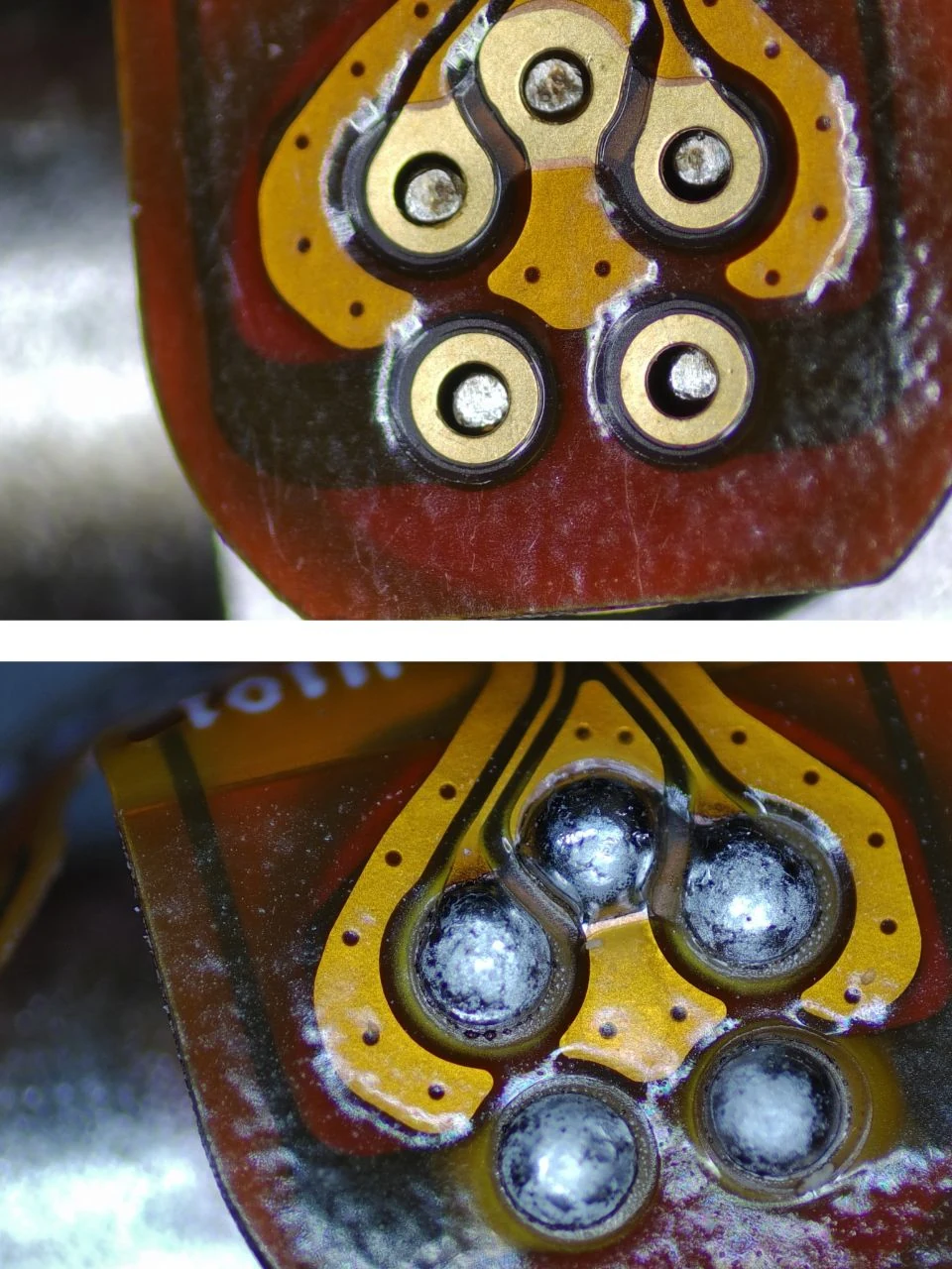
Begin with a specific sample-test question
State what the sample test is intended to decide. The question may concern a single joint location, a small group of locations, a proposed fixture approach, a position-reference concept or the visible result against a customer-defined criterion. Avoid asking a sample to prove that a process is suitable for every version of a product or every future condition. Name the workpiece revision, identify the joint locations to be reviewed and explain which observation will guide the decision after testing. If there is a current process, provide its basic sequence and the reason for evaluating an alternative or localized step. A well-bounded question prevents an observed result from being extended beyond the tested part and helps keep the discussion focused on evidence rather than assumptions. It also distinguishes a first feasibility check from later work that may require additional customer-defined validation.
Send representative workpieces and preserve their context
The physical sample should represent the workpiece condition that matters to the evaluation. Identify the part number or revision, the orientation in which it will be presented, the locations that need processing and any nearby features that limit access or need to remain outside the working area. Provide close photographs that show the complete part as well as the local joint area. When a drawing, layout, pad information or assembly view is available, include it so the target can be discussed without relying on a photograph alone. Explain how the part is currently held, whether it arrives as an individual piece or in a carrier, and which surfaces are available for support. Do not treat a loose demonstration part as equivalent to the intended presentation unless that is the stated test condition. If the supplied samples differ from the intended state, record the difference rather than allowing it to remain implicit.
Describe the joint area and nozzle approach
A sample evaluation needs a clear definition of where the solder is expected to land and how the nozzle can approach that location. Mark the target joint or identify it in an annotated image or drawing. Describe the local pad or terminal geometry, the clearance around the target, the direction from which the workpiece can be approached and any areas that should be avoided. Indicate whether the test involves an isolated location or a repeating pattern, since the available path and workpiece presentation can be different. Include any existing visual reference feature that could serve as a datum. The goal is not to infer suitability from the product category; it is to establish a shared view of the actual connection environment. This information lets the fixture, motion path and any vision reference be considered with the soldering location rather than as separate topics.
Provide solder-ball and process information as test inputs
Supply the solder-ball information that applies to the intended sample, together with any available record of its handling condition and the current joining sequence. The selection should be reviewed against the actual joint geometry and the result the customer expects to inspect; it should not be chosen merely because it was used on an unrelated example. Supplied documentation describes approximately 0.2–0.9 mm solder-ball application for a documented configuration. It also shows 100 W and 200 W laser configuration options. Those references help frame an evaluation conversation, but neither establishes a universal selection or a setting for another workpiece. The documented process sequence is individual ball feed and separation, melting by laser energy at the nozzle, followed by gas-assisted transfer toward the defined position. Describe any existing process steps before and after the proposed soldering action so the sample team can understand the sequence being examined.
Evaluate fixture, datum, motion and optional vision together
A soldering point is only meaningful when the workpiece is presented consistently relative to the nozzle. Provide photographs or sketches of the current holder, carrier or support, and identify the surfaces or features that establish the part position. The evaluation should consider fixture support, motion, datum and, where appropriate, a vision reference as one system. A vision result cannot substitute for an unstable workpiece or an unestablished relationship between a camera feature and the jetting point. Conversely, a stable mechanical reference may be enough for one sample while another may need a defined visual feature for evaluation. Supplied documentation cites ±10 μm vision positioning for one described system. That value is configuration dependent and must remain associated with the fixture, datum, image conditions and application in which it was described; it is not a general accuracy commitment for every part. Use the sample to assess the proposed reference strategy rather than assuming one from a product name or video frame.
Define evidence and acceptance before the trial
Agree on what will be recorded and how the sample result will be judged before testing begins. A concise test record can identify the workpiece revision, target location, part orientation, solder-ball input, fixture arrangement, datum or vision approach, process sequence, observations and inspection method. The customer should provide the acceptance criteria that matter for the application, including the reference drawing, specification or agreed sample appearance where available. A before-and-after image can support discussion of visible change, but it is not by itself a complete qualification for another part or an assertion of electrical, mechanical, reliability or metallurgical performance. If more than one result is being compared, keep the workpiece, reference method and inspection approach identifiable for each sample. This discipline allows a visible result to be connected to the actual test condition and makes it clearer whether the next action is a fixture adjustment, position-reference review, revised process study or further customer-defined validation.
Turn the test outcome into a bounded next step
After the run, review the record against the original test question and the customer-defined acceptance criteria. Separate observations from conclusions. For example, the team may observe the visible location of a deposited solder result under one fixture and reference condition; that observation alone does not establish performance for every workpiece or operating condition. Note what sample was used, what was held constant, what changed and which images or process records belong to the result. The supplied documentation lists up to 6 dots/s for one described system, but that figure is a documented maximum rather than a complete cycle time or a production conclusion for the tested part. Likewise, a supplied frame demonstrates 0.25 mm solder-ball processing on a 0.4 mm pitch test pattern only. It should be used as a stated demonstration, not as a universal pitch, speed or application claim. The next step should remain proportionate to the evidence: refine the sample setup, review a different datum or fixture, compare defined inputs, or proceed to the additional validation required by the application owner.