
Define the assembly before describing a process capability
The phrase 3D electronic assembly can describe a workpiece whose soldering targets must be considered as positions within the actual assembly rather than as a generic category. It does not, by itself, establish that any particular product can be processed. A useful engineering discussion starts by identifying the intended soldering position, the way the workpiece can be presented, and the reference from which that position will be found. The practical question is whether a consistent relationship can be established between the nozzle and the defined workpiece position for representative parts. That question should remain separate from broad claims about 3D capability, product type, production suitability or qualification. Photographs, drawings where available, a description of the intended soldering locations, representative samples and customer-defined acceptance criteria create a clearer basis for review. They allow the process discussion to be about the actual assembly rather than an assumed class of electronics. If more than one location is involved, each location should be understood in relation to the chosen datum and fixture concept. A result observed at one location does not automatically define the result at another location, even when both belong to the same assembly.
The documented solder-ball sequence
The supplied process description has a defined sequence. First, an individual solder ball is fed and separated. The separated ball is then melted at the nozzle by laser energy. Gas-assisted transfer moves the molten solder toward a defined workpiece position. This description is intentionally narrower than a claim about every assembly outcome: it identifies how solder is presented and transferred in the documented process. The sequence makes the relationship between the selected ball, the nozzle and the workpiece position an important evaluation topic. It also means that a laser source should not be considered in isolation from ball delivery and transfer. For an assembly with spatially defined positions, the engineering review should examine how the individual delivery event relates to the target position in the actual fixture arrangement. The supplied process and CCD videos can show this kind of process context. They are useful for understanding the documented sequence and head-to-workpiece relationship, but they are not customer cases, proof of suitability for an unrelated design, or universal production evidence. A process description becomes meaningful only when it is connected to the actual assembly, its intended position reference and the acceptance criteria agreed for the evaluation.
Fixture, motion and datum form one reference chain
For an assembly that must be evaluated in three-dimensional space, fixture, motion and datum should be considered together. The fixture is part of how the workpiece is presented; the datum is the reference used to relate the workpiece to the intended position; and motion is part of how the process head is brought into that relationship. Treating any one of these items as independent can obscure the actual process question. A suitable fixture concept for evaluation is one that makes the selected datum usable for the particular sample and leaves the documented process relationship available for review. The motion approach should be discussed with the fixture and datum, not inferred from a general machine description. This is especially important when several soldering positions must be reviewed, because the reference used for one position needs to remain meaningful at the next. The aim is not to assume a fixed solution for all spatially arranged assemblies. It is to define a reference chain that can be checked on representative samples. Any changes in the way the workpiece is presented, held or referenced should be treated as process-evaluation inputs. The final fixture and motion arrangement should follow sample validation and the customer-defined acceptance criteria rather than an image, a general product label or an isolated specification value.
Use vision as an evaluated reference option
Vision may be included when image-based reference is useful for the defined workpiece position. It is an optional part of the evaluation, not a substitute for a meaningful datum or fixture. Where vision is considered, the feature being referenced, the relationship between that feature and the soldering position, and the way the workpiece is supported all belong in the same review. The supplied documentation states ±10 μm vision positioning for one described system. That figure is configuration dependent and should remain tied to that described system and its conditions. It is not a universal positioning statement for every camera setup, fixture, workpiece or spatially arranged assembly. An evaluation can therefore ask a more useful question than whether vision is present: does the chosen reference method establish the required relationship for this sample and its acceptance criteria? In some cases a fixture datum may be the relevant reference; in others, vision may be assessed as part of the setup. Neither route should be assumed from the assembly label alone. Supplied CCD material illustrates real process and interface context, but it does not establish an accuracy claim for an untested application. The reference method should be recorded alongside the fixture and motion approach so that the sample result can be interpreted within its actual conditions.
Keep ball size and fine-pitch evidence in documented context
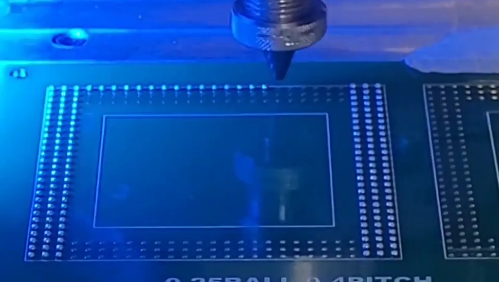
The supplied documentation describes approximately 0.2–0.9 mm solder-ball application for a documented configuration. This is useful configuration-scoped information, not a universal machine limit, a recommended range for every workpiece or a conclusion about a particular three-dimensional assembly. The selected ball must be evaluated with the actual soldering position, the presentation of the workpiece, the defined datum and the desired sample result. A separate supplied frame demonstrates 0.25 mm solder ball processing on a 0.4 mm pitch test pattern only. Its factual value is limited to that demonstration. It does not establish a universal minimum ball size, minimum pitch, access envelope or capability on another product. These limits on interpretation matter because a spatially arranged assembly can introduce a different fixture and position relationship from the test pattern shown in the frame. The image can support a transparent discussion of the supplied process evidence, but it cannot replace evaluation of the intended workpiece. A careful process review separates what is documented from what remains to be tested: documented ball-application context on one configuration, a documented test-pattern demonstration, and application-dependent selection for the customer’s own samples.
Read configuration values without turning them into promises
The available documentation references 100/200 W laser configuration and a maximum frequency of up to 6 dots/s for described configurations. Both references are configuration dependent. They should not be combined into a universal machine specification, an assembly-level performance promise or a statement about a different product. The 100/200 W reference identifies documented laser configuration options; it does not select the appropriate condition for an untested workpiece. Similarly, up to 6 dots/s identifies a documented maximum frequency rather than a complete description of an application’s full operating sequence. A spatially arranged workpiece may require its own evaluation of fixture, datum, motion and optional vision before a process approach can be discussed responsibly. The documented values can be retained as starting context when their scope is stated plainly. They should not be used to infer accuracy, reliability, yield, qualification, thermal behavior, material compatibility or overall throughput. A configuration proposal, if appropriate after sample work, should state its assumptions and the criteria used to review the samples. The final machine configuration follows application and sample evaluation, not an attempt to extrapolate a configuration value into a universal outcome.
Build evidence through sample validation
Sample validation is the point at which a general process explanation becomes an assembly-specific engineering review. Representative samples allow the fixture, motion, datum and any vision approach to be considered with the actual defined soldering positions. The evaluation should identify what will be reviewed and what customer-defined acceptance criteria apply before conclusions are drawn. Supplied sample images and videos can provide visual process context, yet they are not approved customer cases and do not establish customer results, qualification or a result for an unrelated assembly. A visible sample result should therefore be read as evidence from the stated sample conditions, not as a universal guarantee. The process record should distinguish documented configuration information from observations made during the sample work. It should also note any remaining questions that the customer’s acceptance criteria require the parties to address. This keeps the outcome technically useful without overstating what a demonstration or single evaluation can show. If the process is taken further, the configuration discussion can be based on the validated workpiece relationship and the agreed evaluation evidence. That sequence respects the fact that localized solder-ball delivery, fixture support, motion, datum and optional vision are interdependent elements of one application-dependent process.