
Begin with the defined workpiece position
For a sensor or MEMS workpiece, the useful starting question is not whether the category is generally suitable for laser soldering. The useful question is which physical position is to receive the transferred solder and how that position will be presented to the process. The documented sequence moves molten solder toward a defined position; it does not make a category-level claim about every device called a sensor or MEMS. A process proposal therefore needs a visible relationship between the intended position, the support for the workpiece, the selected datum and the nozzle approach. This distinction matters because a nominal program coordinate is not, on its own, the real target. The workpiece must be supported, the fixture must establish its relationship to the machine, and the motion path must bring the process head into the planned location. Where vision is included, it participates in that same arrangement rather than becoming a substitute for the fixture or datum. The documented facts support a discussion of this positional chain. They do not establish that an unreviewed workpiece can be soldered, that nearby features are unaffected, or that a visible sample result applies to another design.
Treat one solder ball as one controlled process input
The sequence begins before laser energy is applied. Individual solder balls are fed and separated so that a ball is available for the soldering event. This is a distinct process step, not background handling. The separated ball is the input that reaches the nozzle and is then melted there. Thinking in this order prevents an evaluation from being reduced to a laser setting or a positioning number. Delivery, separation, nozzle relationship, transfer and workpiece position are connected parts of one event. A ball diameter may be considered as part of the application discussion, but its role must stay tied to the actual position and intended result on the workpiece. The supplied system information describes approximately 0.2–0.9 mm ball application for a documented configuration. That is useful configuration context, not a universal operating range, a size recommendation for a sensor or MEMS part, or proof that every proposed location fits within that range. A ball value should not be used alone to predict a solder result, materials compatibility or acceptance on a different assembly.
Separate melting at the nozzle from transfer toward the target
The documented laser action is specific: laser energy melts the solder ball at the nozzle. Gas assistance then transfers the molten solder toward a defined position. Keeping these two actions distinct makes the process easier to describe accurately. The laser is not simply a general statement about an assembly, and gas assistance is not an independent positioning system. Together they are part of the delivery event that follows individual-ball feeding and separation. The word toward is also important. It describes the supplied transfer fact without promising a result that has not been evaluated. The resulting application still depends on the way the workpiece is held and referenced, on the planned motion relationship and on the conditions selected for that application. The documented process sequence supports an assessment of a localized soldering event at an intended location. It does not establish a universal thermal effect, a specific metallurgical condition, a material set, an acceptable joint appearance, or the suitability of every sensor and MEMS design. Those are not conclusions that can be drawn from nozzle melting and gas-assisted transfer alone.
Build the positional chain from fixture, motion, datum and optional vision
A defined position is produced by several cooperating elements. Fixture support holds the workpiece in the required presentation. A datum establishes the reference relationship. Motion moves the process head relative to that supported, referenced workpiece. Vision can be included where the configuration calls for it. The process should be described as this combined chain, because none of its elements provides the entire positional relationship by itself. The supplied documentation cites ±10 μm vision positioning for one described system. The number should retain all of that scope: it is a vision-positioning figure for one system, not a general positioning claim for every camera, fixture, datum, motion path, sensor or MEMS workpiece. In particular, it should not be converted into a claim about the location of transferred solder on a new part, because the complete position chain remains application dependent. The proper technical use of the figure is to identify a documented system reference while defining the fixture, datum, motion and any vision arrangement for the proposed workpiece. This framing also clarifies the place of a supplied process frame. It can show a supported workpiece during localized laser soldering and help explain the nozzle-to-workpiece relationship. It cannot show qualification, reliability, an across-the-board accuracy result, or a conclusion about a component not represented in the frame.
Use configuration figures as context, not as a recipe
Published figures are useful only when their configuration limits stay visible. The supplied information identifies a 100/200 W laser configuration, approximately 0.2–0.9 mm ball application, up to 6 dots/s, and ±10 μm vision positioning for one described system. None of these values is a universal specification. They belong to a documented configuration and cannot be combined into a generic process promise for sensor or MEMS workpieces. The 100/200 W reference identifies laser configuration, not an application setting, a temperature conclusion or a statement about any component material. The ball range identifies approximate application scope for the described configuration, not a recommendation for every joint. Up to 6 dots/s is a stated maximum process-frequency reference for that configuration; it is not a complete cycle time. A complete workpiece sequence may involve support, datum establishment, motion and optional vision in addition to the soldering event, so the dot-rate figure alone cannot state process duration or production output. The vision value likewise remains limited to the described system. Keeping each figure in its own context is more accurate than presenting a list of numbers as a capability guarantee.
Keep the test-pattern footage in its documented scope
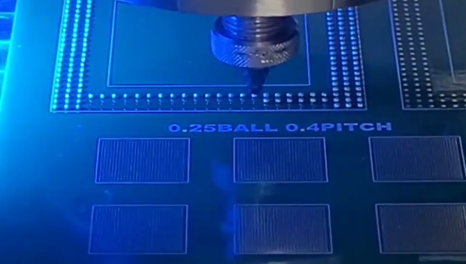
The supplied footage marked 0.25 mm ball / 0.4 mm pitch documents a test-pattern demonstration only. Its supported meaning is narrow: it shows 0.25 mm solder ball processing on a 0.4 mm pitch test pattern. It is not evidence of a universal minimum pitch, a minimum supported ball size, a positioning limit, a production rate, or a result on a sensor or MEMS workpiece. This is a useful boundary for reviewing visual evidence. A demonstration can show process context, including the presence of a ball, nozzle and target pattern. It does not reveal the full application arrangement for an unrelated workpiece. It should therefore be captioned and discussed as a test pattern, rather than repurposed as proof of broad fine-pitch compatibility. The same principle applies to any supplied image of workpiece support: the frame can illustrate a process relationship, but it cannot substitute for the actual fixture, datum and position strategy required for the workpiece under consideration.
Organize the application review around what is known and what must still be shown
A responsible review starts by recording the proposed soldering position and the way the workpiece will be supported. It then maps the datum and motion relationship, identifies whether vision is part of the proposed arrangement, and describes the documented feed–separate–melt–transfer sequence. This produces a clear separation between the known process facts and the choices still specific to the new application. The result is a technical discussion that can be checked against representative workpieces rather than against a generic category label. The review should keep observations proportional to the available evidence. The documented facts establish individual-ball feeding and separation, melting at the nozzle, gas-assisted transfer toward a defined position, and the combined role of fixture, motion, datum and optional vision. They establish configuration-scoped reference values as described above. They do not establish customer examples, yield, qualification, standards compliance, materials compatibility, reliability, cycle time, metallurgy or a universal thermal conclusion. A process decision should therefore describe the tested arrangement and customer-defined acceptance criteria without extending its claim beyond the application that has actually been reviewed.