
1. Describe the automation project as a process relationship
Begin by naming the relationship the equipment must control: a solder ball is delivered to a nozzle, the nozzle and workpiece are brought into a defined relationship, the ball is melted there, and gas assistance transfers molten solder toward the defined position. That statement is more useful than starting with a machine name or a single capacity figure because it identifies the elements that have to be specified together. The project brief should say what is fixed, what moves, and what feature or datum establishes the intended soldering position. It should also distinguish required functions from optional ones. A fixture, a programmed motion path and a datum are part of the positional arrangement; vision is an additional reference method only when it is needed for the stated arrangement. The specification should not imply that one element replaces all of the others. A camera image does not itself define the physical workpiece relationship, and motion coordinates do not themselves state the datum. Keeping those roles separate makes the requested automation scope legible before configuration choices are discussed.
2. Set out the documented solder-ball sequence in order
The sequence should be written in the same order in which the documented process operates. First, solder balls are fed. Individual-ball separation then isolates a ball for the next action. The ball reaches the nozzle, where laser energy melts it. Gas-assisted transfer moves the molten solder toward the defined position. The fixture, motion system and datum maintain the intended relationship between the process and the workpiece; where specified, vision contributes to positioning. This sequence gives the project team a simple basis for deciding what needs a description in the automation concept. For example, it separates ball handling from melting, melting from transfer, and transfer from workpiece positioning. Those are connected actions, but they are not interchangeable labels. A specification that merely requests “laser soldering” leaves the delivery and reference parts unclear. A specification that names each documented action tells a reviewer whether the proposed system addresses the entire process relationship. It also makes it easier to mark which items are application-defined rather than treated as built-in assumptions.
3. Keep ball diameter and pitch references in their stated scope
Ball size should be described as a project selection, not as a number copied from unrelated footage. The supplied documentation refers to approximate 0.2–0.9 mm ball application for a documented configuration. That statement is useful as a configuration-scoped reference, but it is not a universal range, a recommendation for every joint or a commitment that every automation project uses the same ball sizes. The project document can therefore record the ball diameter under review and state whether it falls within the scope of the specific configuration being considered. It should not convert an approximate reference into a guaranteed limit. The supplied 0.25 mm ball / 0.4 mm pitch footage needs an even narrower description: it is a test-pattern demonstration of 0.25 mm solder ball processing on a 0.4 mm pitch test pattern. It is not evidence of an unspecified minimum pitch, general component capability or result on another design. Treating the footage as a labelled demonstration preserves its value without assigning claims that the source does not make.
4. Specify the positional reference chain before selecting vision scope
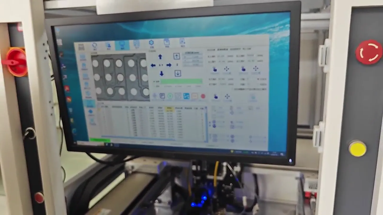
Automation requires a declared way to relate the defined position to the workpiece. The source facts support a combined arrangement of fixture, motion and datum, with vision optionally working with them. The specification should state the fixture role, identify the chosen datum and state how motion is expected to use that relationship. If vision is requested, the document should state that vision is part of the positioning arrangement rather than describe it as a standalone guarantee. This keeps the workpiece reference visible in the project definition. The supplied material cites ±10 μm vision positioning for one described system. Use that wording only with the qualification that it belongs to that one system and its associated configuration. Do not carry the value into every proposed fixture, workpiece, datum or automation cell. A precise request is therefore not “provide ±10 μm on all parts.” It is “define the required positional reference, identify whether vision is included, and describe the configuration under which any positioning figure is being cited.” This phrasing links the number to the mechanism and avoids treating a documented value as a universal outcome.
5. Separate laser configuration from an implied process conclusion
The documented system includes 100/200 W laser configuration. In a project specification, that information should appear as a configuration reference, not as a claim that either value is required, sufficient or applicable to every assembly. The verified process fact is that laser energy melts the solder ball at the nozzle. Beyond that, the project should ask for the selected configuration to be identified rather than infer a result from a power label. This distinction matters because a laser configuration is only one item in the connected sequence. Ball feed and separation, nozzle melting, gas-assisted transfer, fixture support, motion, datum and any vision arrangement still need to be described. A request can therefore list “laser configuration: to be identified for the proposed system” and preserve the documented 100/200 W reference in a notes field with its configuration limitation. It should not create a numerical energy setting, a heating claim, a materials claim or a thermal conclusion that the supplied information does not support. The purpose of the specification is to make the selected arrangement explicit, not to turn a configuration option into a universal specification.
6. Treat dot frequency as a limited configuration reference
The source describes a maximum frequency of up to 6 dots/s for a described system. This may be relevant when a project needs to compare the stated soldering action with its planned sequence, but it is not a complete automation-cycle figure. It does not state loading, part presentation, fixture action, datum establishment, motion travel, optional vision activity or any other project-specific step. For that reason, the specification should record the value in a dedicated “documented configuration reference” field and state exactly what it represents: a maximum soldering frequency for the described system. It should not be relabelled as a guaranteed output, an overall cycle time or a result for a different configuration. The project can separately list the sequence steps that are in scope and ask that their timing be addressed for the proposed arrangement, without inserting an unsupported numerical cycle time. This approach is both more useful and more accurate. It gives the reviewer a visible process sequence to consider while preserving the boundary around the only documented frequency figure.
7. Assemble a reviewable project brief and evidence record
The final project brief should combine the process sequence with its evidence boundaries. Include the defined soldering position; the fixture, motion and datum arrangement; whether vision is included; the proposed ball reference; the laser configuration to be identified; and the stated role of gas-assisted transfer. Then place each supplied figure in a clearly labelled reference area: approximately 0.2–0.9 mm ball application for a documented configuration, up to 6 dots/s for a described system, ±10 μm vision positioning for one described system, and 100/200 W laser configuration. Each entry should retain its qualifier. A separate note should identify the 0.25 mm ball / 0.4 mm pitch footage as a test-pattern demonstration only. This format allows a reader to see what the source establishes and what remains to be defined for the proposed automation project. It also avoids unsupported statements about customer use, production yield, qualification, reliability, materials compatibility, standards, metallurgy, cycle time or thermal behavior. A complete specification is not the longest list of figures; it is the clearest account of the requested process relationship and the limits of the available evidence.